 |
By : G.Kuhn
March 2004
Radio control electronics has always fascinated me, and through the years I've built numerous odds and ends, including an encoder. My favourite analogue chip, the NE5044, has been obsolete a while now. Fortunately Pics, and Internet, came along, but Microchip Assembler was more Greek to me than any foreigner from that country!
At the best I could flash a LED, and pretty much resigned to using other people's compilations. I've been looking longingly at all the Basic compilers out there, but alas, that is like having Champagne taste on a Beer budget :-)
A modern RC encoder, whether it be for an AM or FM system, would typically produce of a number of pulses corresponding to the number of channels, plus a longer sync pulse to enable the decoder at the receiver end to extract the pulses in the correct order.
This combined pulse train is called a Frame, and is approximately 20 milliseconds long. A typical channel pulse at neutral is 1.5 milliseconds long, and consists of a variable high for 1100 microseconds, and a fixed low of 400 microseconds. The fixed low is required by most AM receivers for automatic gain control.
The decoder circuit will look at the pulse length from rising edge to rising edge, so we only need to vary the high, giving a combined pulse from 1000 microseconds to 2000 microseconds, for full travel of the control stick.
An actual control stick only moves about 90 degrees, so the voltage swing is small. This is the reason for the rather complicated maths done on the ADC value.
I've also scaled the equation to enable an eight bit A to D pic to be used. ( 16C711) A great advantage of using the ADIN function instead of POT, is that the channels can be mixed or reversed externally. Obviously this could also be done in software, but that is beyond my abilities at this moment ( nor with 30 lines of code !!!).
Another issue to address is the terms Fixed Frame Rate, and Variable Frame Rate. This code produces a Variable Frame Rate, as the varying pulse lengths add or subtract from the total Frame time. This would be easy to fix with more code. Most modern decoders are quite happy with both, but a "nice to have" would be a link on the encoder board, to change from one to the other.
NB : The original code was written by G.Kuhn for Let Pic Basic Pro Lite.
|
NB : To develop a full 8 channels version, just add 4 '5K' pots to ADC4-7 and use the PROTON code
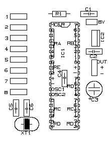
Board Print in TCI3.1 format (see How To concerning PCB design to get and use TCI freeware)
 |
 |
(Normal) (Mirrored)
 |
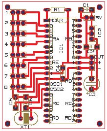 |
| R1 : 10K (0.25w) | IC1 : 16F877 |
| C1,C2,C4 : 100nF | IC2 : 7805, 78L05 |
| C3 : 10 uF | |
| C5,C6 : 22pF | XT1 : Xtal 4Mhz |
| P1 to P8 : 5K (pot, sticks,...) | 9 x 3 pins connectors |
| 1 x 2 pins connector |
Developed by G.Kuhn in February 2004
(Last edition 3/3/04)
Crownhill's Proton Plus Compiler is a part of the Proton Development Suite - A suite of British-developed applications enabling fast development of PICmicro's using the PICBASIC Language.
For more information on the Proton Development Suite, please visit www.picbasic.org
Please note that this project is published AS IS. No responsibility of the author in any cases can be invoqued. This project is for learning and entertainment purpose only. No vital application can be connected to it. As this project is published on a free and friendly base for the user site of PROTON +, it cannot be used in any condition for business or commercial use without explicit permission of the author.