 |
Stoboscope
By Olivier de Broqueville And Tim Box
|
Introduction :
The purpose of this project is to create a tuning device for motors.
The stroboscope converts high voltage pulse from the coil into TTL level pulse a PIC 16F628 will use to calculate RPM, add the desired dwell and trigger a flash unit.
How it works
The module is composed of 3 parts.
Some maths
Here are some basic elements for a 4 strokes combustion motor:
First, as it is a 4 strokes, you need 2 revolutions to complete a cycle (Down= admission, Up=compression, Down=explosion, Up=burned gas evacuation). If we look only to the first cylinder, this means that the period of the spark is: (2 revolutions * 60 seconds)/RPM => P= 120/RPM with RPM beeing Revolution Per Minute.
As DWELL is calculated as an angle in degree, 2 revolutions are also equal to 2*360° => 720°
But the PIC has to use a delay, not an angle as by adding a delay between detection of the pulse and the moment you trigger the 'flash' you add a dwell. Then:
Angle (dwell)= 720*(delay/period) where delay and period are here in Ms but have only to be expressed in the same 'unit'.
This means that you have to know the RPM or better, the frequence of the sparks on Cyl. 1 (Cyl 1 is, by convention, the cylinder reference used by manufacturers). This is exactely what the RPM routine (written by my friend Tim) does.
Then, based on the by you inputed DWELL (in degree) and the by the PIC calculated frequency knowing that Freq.=1/period we get:
DelayMS=(Dwell/720)*(1/Freq)
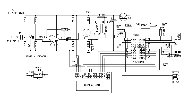
Schematic :
 |
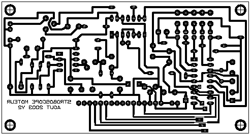
PCB :
Board Print in TCI3.1 format (see How To concerning PCB design to get and use TCI freeware)
 |
 |
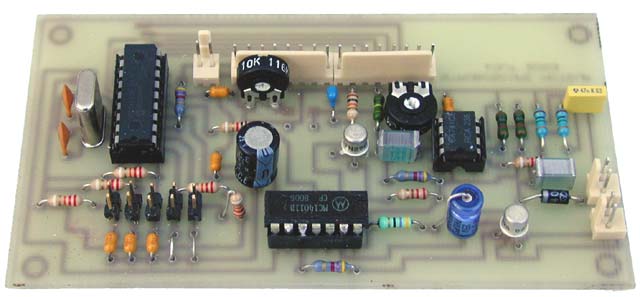
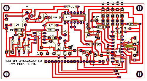
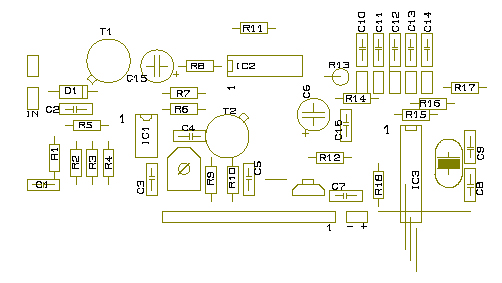
The PCB and Components:
 |
 |
The
Component list:
| R1-R2 : 1M | T1-T2 : 2N2905A |
| R3-R4-R10 : 10K | IC1 : 741 |
| R5-R12 : 1K | IC2 : CD4011 |
| R6-R11-R18-R13 : 4K7 | IC3 : PIC 16F628 |
| R7 : 220R | |
| R8 : 47R | D1 : 1N4007 |
| R9 : 100K | |
| R14-R15-R16-R17 : 8K2 | Xtal : 20Mhz |
| C1 : 47nF | Alphanumeric LCD 2x16 car. compatible PROTON |
| C2-C4 : 220nF | |
| C3-C7-C13-C14-C16 : 100nF | AJ1 : 100K |
| C5 : 4.7nF | AJ2 : 10K (LCD adjust) |
| C6 : 220 uF 25V | POT1-POT2 : 5K lin |
| C8-C9 : 22pF | |
| C10-C11-C12 Are replaced by straps | 3 switches |
| C15 : 47 uF 16V |
The
program:
(To be completed)
Adjustment:
The only hardware adjustement is the sensitivity of the input pulse amplifier. This can be adapted by turning AJ1.
It is obvious that the darkness of the LCD can also be adapted by AJ2.
The coil is up to you. What you need is 10 to 20 turns of a insulated copper wire you can place around the wire of Spark plug of Cyl 1. You can do this by wiring the coil on a piece of plastic tube of such a diameter you can pass the wire of the plug through it. The only requirement is that the support cannot be metalic. I recommand that you use shielded cable between the captor and the module. I even tried with one of those 'telephone' captors, used to record phone conversations. It worked too.
I hope this will helps you to go further in car tuning. Or, why not, to imagine your own circuitry and post it here...
Developped by Olivier de Broqueville in September 2003
(Last revision 10/11/03)
Please note that this project is published AS IS. No responsability of the author in any cases can be invoqued. This project is for learning and entretainment purpose only. No vital application can be connected to it. As this project is published on a free and friendly base for the user site of PROTON +, it cannot be used in any condition for business or commercial use without explicit permission of the author.