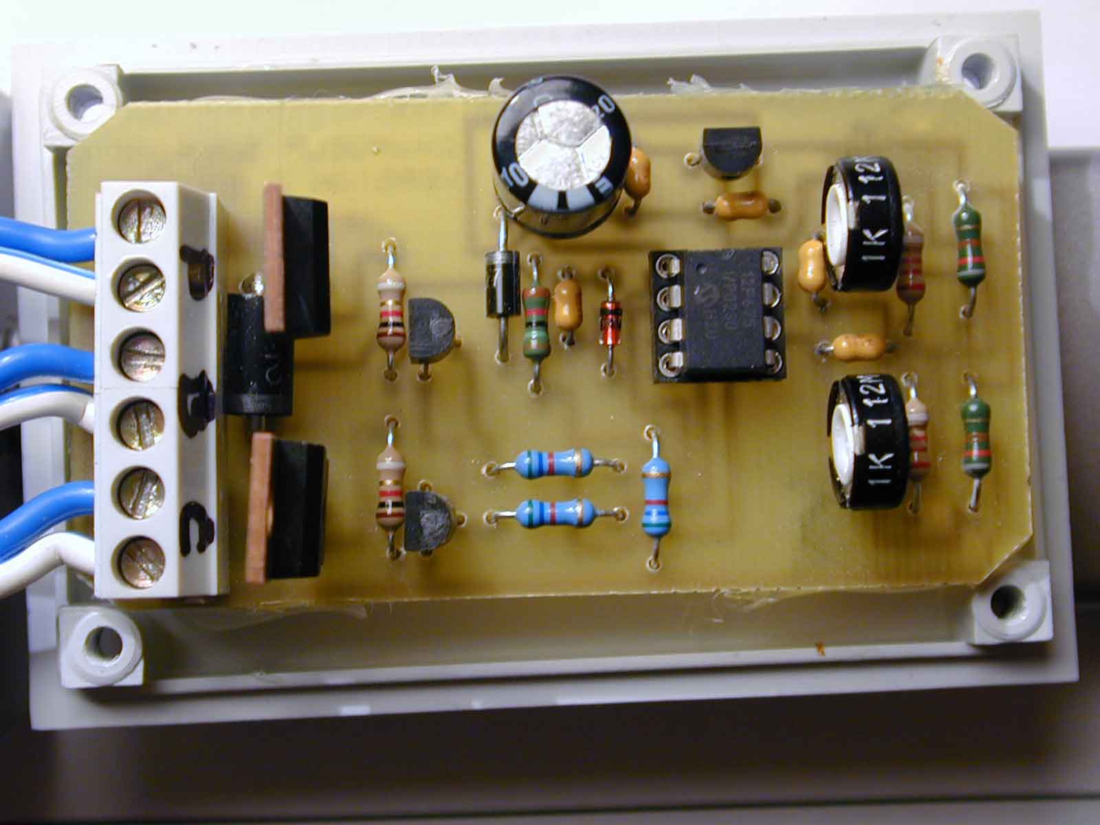
By Olivier de Broqueville

The purpose of this project is to realize a Solar panel controller. Initially developed for a sailing boat, the target to reach was to control the level of charge and discharge and to protect a 12 volts lead battery connected to a 32 watts solar panel.
The project is based on a 12F675 and uses HEXFETs to switch the load and the solar panel. The programs were developed with PROTON+ and around 10 of those small devices are today doing their job without any problems. The use of a PIC processor gives a large access to the way the load is used (with or without over voltage protection) or how the controller reacts when the full charge level is reached. This gives a lot of improvement possibilities.
This project has absolutely not the intention to show the best and most effective way to program. After all, I am a hobbyist too. It is a example of how to solve quickly a problem with a small and robust realization.
The notions used here are:
ADIN on multiple IO pins
some basic maths
Because it is small, cheap and has AD conversion. It is also a Flash device, which means you can experiment with it and reprogram when needed. (see datasheet at www.microchip.com)
Do I really need to answer to this? Just try to adapt this realization for your own needs and it will be clear for you. BASIC is surely the best, easiest and natural way to do it. The commands and directives proposed by the PROTON compiler feed nearly all imaginable situations. Even if I recognize that there are situations where assembler is needed, BASIC is and remains so much easier.
There is a Free Lite Edition available from the Proton Website
Here I have to confess that this ‘last’ release of the schematic is ‘loosely’ inspired by an article published in Electronique Pratique No. 272. Although the switching devices, the processor the board and the program are different and act differently… Which, after all, is a lot….
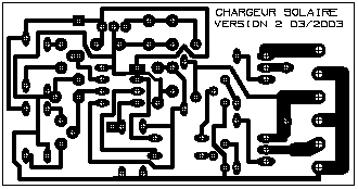
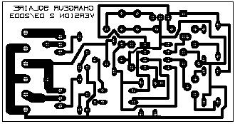
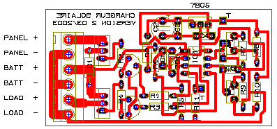
Board Print for TCI3 (see How To concerning PCB design to get and use TCI freeware)
 |
 |
 |
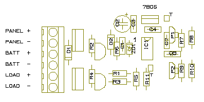 |
| R1-R3 : 6.2K | D1 : schottky 3A (1N5821,…) |
| R2-R4 : 1K | D2 : 1N4007 |
R5 : 5.6K |
DZ1 : Zener 4,7V 0.5w |
R6 : 15K |
IC1 : 12F675 |
R7-R9 : 2.2K |
IC2 : 7805 |
R8-R10 : 820R |
T1-T2 : BC547B |
R11 : 10k |
T3-T4 : IRF9540 (MOS P) (or equ.) |
P1-P2 : 1K |
|
C1,C3,C4,C7,C8 : 100nf |
|
C2 : 470uF 25V |
Two programs are included. Both perform the same task.
The first one does NOT use ADIN as such and addresses explicitly the needed registers of the PIC. It is given for reference only although it works OK. It gives a more comprehensive view of how to access registers . It is a bit longer but easier to understand.
The second one is a more compact version using ADIN. A specific adjustment routine is also added which can be triggered by setting HIGH the test PIN (GPIO 3) . It disables all hysteresis and delays routines in order to give immediate reactions and facilitate settings and adjustments.
Explanation:
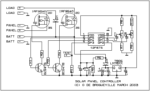
The schematic is divided in two main parts if we except the 'brain', the PIC. One part is checking voltages through resistors bridges. LOW reference is centered on P1, HIGH reference is centered on P2. Both resistor bridges are powered by regulated 5Volts and therefore independent from the battery voltage. The last bridge is dedicated to the battery voltage. The PIC will convert those 3 voltages and compare the battery voltage to the 2 references. The PIC will then take actions.
The different tasks performed by the program burned in the PIC are quite simple and do not require a lot of code space. It gives you the opportunity to improve or adapt the original code for your own purpose.
What does the program do:
The two programs are documented and self explanatory.
To set the desired LOW and HIGH voltage reference, a test mode is foreseen. Why? Because in normal operation mode, the PIC performs actions with delays. This to avoid to open and close the Battery and Load 'gates' in a sort of pumping effect. The load consumption, modifying the battery voltage, creates an interaction around the 'switching' point. Moreover, to lower the intrinsic consumption of the module.
This delay process makes the adjustment process a bit difficult. By puting the TEST point at +5volt, you inform the pic to run the ADJUSTMENT routine, means without delays.
To adjust the reference values:
Set TEST point to HIGH to enter ADJUSTMENT mode
Use a adjustable POWER SUPPLY ; Connect it in place of the BATTERY
Set POWER SUPPLY to 10.8 volts. Adjust P1 to get a LOW level on GPIO.4 (pin 3). This means that the 'Load' is disconnected below 10.8 volts (or other reference suitable for your needs)
Set POWER SUPPLY to 13.8 volts. Adjust P2 to get a LOW level on GPIO.5 (pin 2).This means that the 'Solar Pannel' is disconnected above 13.8 volts (or other reference suitable for your needs)
By varying the POWER SUPPLY voltage, check that :
Below 10.8, GPIO.5 is HIGH and GPIO.4 is LOW(Solar Panel connected but Load disconnected)
Between 10.8 and 13.8, GPIO.5 is HIGH and GPIO.4 is HIGH (Solar Panel AND Load connected)
Above 13.8, GPIO.5 is dLOW and GPIO.4 is HIGH (Solar Panel disconnected and Load connected)
When this is OK, disconnect TEST point from +5 volts to go back in Normal Mode.
On the different prototypes, the typical power consumption of the module was around 5 to 7 ma/h.
Developped by Olivier de Broqueville in March 2003
(Last revision 10/11/03)
Crownhill's Proton Plus Compiler is a part of the Proton Development Suite - A suite of British-developed applications enabling fast development of PICmicro's using the PICBASIC Language.
For more information on the Proton Development Suite, please visit www.picbasic.org
Please note that this project is published AS IS. No responsibility of the author in any cases can be invoqued. This project is for learning and entertainment purpose only. No vital application can be connected to it. As this project is published on a free and friendly base for the user site of PROTON +, it cannot be used in any condition for business or commercial use without explicit permission of the author.