
You can download the original PDF file for printing and offline viewing, here
With Christmas fast drawing near, I thought it appropriate to create a project that has a festive theme and also shows what the humble PICmicro is capable of doing with a little imagination and the right tools. i.e. PROTON+ Compiler.
Everyone and their reindeer has created Christmas projects in the past but most of them revolve around multi-coloured flashing LEDs. Don’t get me wrong, there’s nothing wrong with flashing LEDs, but let’s face it, they don’t exactly stimulate the imagination?
So what I’ve created for your perusal is a project to play several well known Christmas tunes using 3 channel (polyphonic) sound, with each channel having a pleasant chime effect. And all this using nothing more than a handful of common or garden components that you probably already have lying around. And yes, you can flash LEDs while the music is playing if you wish!
Creating sound on a PICmicro is not difficult, simply toggle a pin rapidly enough and it will produce a square wave output. Adjust the rate of toggle and the frequency will alter. However, nothing else can be accomplished if this crude method is adopted because the PICmicro will use all its resources servicing the bit being toggled. So we must use an interrupt in order to toggle the pin in the background, while the main program goes about its business as usual.
The program listing below illustrates a method of producing a tone from pin PORTB.0 using a TIMER1 interrupt.
' Program PLAY_NOTE.BAS
      ' Produce a tone from PORTB.0 using a TMR1 interrupt
      Device = 18F452                     ' Use a PIC18F452 device
      XTAL = 20                           ' With a 20MHz crystal/resonator

      Dim NOTE_COUNTER as Word SYSTEM     ' Determines when the pin is toggled
      Dim NOTE as Word SYSTEM             ' Determines the pitch of the note
      Dim TIMER1 as TMR1L.Word            ' Combine TMR1L/TMR1H as a 16-bit word
      Symbol GIE = INTCON.7               ' Global Interrupt Enable/Disable

      ON_INTERRUPT Goto NOTE_INT          ' Point interrupts to our interrupt handler
      Delayms 400                         ' Wait for PICmicro to stabilise
    ALL_DIGITAL = True                  ' Set PORTA and PORTE to digital
Goto OVER_INTERRUPT ' Jump over the interrupt handler
'----[INTERRUPT HANDLER]------------------------------------------------
      NOTE_INT:
      TIMER1 = 65490                      ' Load TMR1 with a preset value
      Inc NOTE_COUNTER                    ' Increment the note counter
      If NOTE_COUNTER >= NOTE Then        ' Is it time to toggle the pin ?
      PORTB = PORTB ^ 1                   ' Toggle pin PORTB.0
      Clear NOTE_COUNTER                  ' Clear the note counter
      Endif
      Clear PIR1.0                        ' Clear TMR1 interrupt flag
      Retfie FAST                         ' Exit the interrupt
      '----[MAIN PROGRAM CODE]--------------------------------------------------
      OVER_INTERRUPT:
      Output PORTB.0                ' Make PORTB.0 and output
      Clear NOTE_COUNTER            ' Reset the note counter
      T1CON = %00000001             ' Turn on TIMER1, with a 1:1 prescaler
      Clear PIR1.0                  ' Clear TMR1 interrupt flag
      Set PIE1.0                    ' Enable TMR1 as peripheral interrupt source
      INTCON =  %11000000           ' Enable global interrupts, peripheral interrupts
      NOTE = 0                      ' Reset the note to play
      Repeat                        ' Create a loop
      Inc NOTE                      ' Lower the pitch of the note
      Delayms 50                    ' Wait 50ms between notes
      Until NOTE = 1000             ' Stop when we reach a count of 1000
      Clear GIE                     ' Disable interrupts to stop the note
Stop
The program above is very simple in principle. A TIMER1 interrupt is implemented by setting the appropriate registers and pointing the compiler’s interrupt handler to the interrupt subroutine. Whenever TIMER1 overflows. i.e. reaches a value of 65536, an interrupt will be triggered and the NOTE_INT subroutine will be ran.
Within the NOTE_INT subroutine, TIMER1 is preloaded with a value to ensure that another interrupt will occur quickly. A counter variable is then incremented (NOTE_COUNTER) and tested against the required note frequency (NOTE). If both variables are the same then PORTB.0 is toggled by XORing it with itself, and the counter is reset ready for the next occurrence of the interrupt. However if the variables are not equal to each other then the TIMER1 interrupt flag is cleared and the interrupt is exited without doing anything. This happens in the background of the program so placing a value in the variable NOTE will alter the rate of the toggle on PORTB.0 thus increasing or decreasing the frequency of the square wave produced.
The circuit shown below can be used for the program above.
Although the previous program does what it should do and produces a note of varying frequency, it isn’t exactly pleasing to the ear. What’s required is a form of envelope shaper in order to give the note a more mellow sound. This is achieved by taking advantage of a well known method of charging a capacitor and allowing it’s voltage to decay naturally. While the capacitor is fully charged, the note is at full volume but as the capacitor discharges, the note’s volume will decrease until it is silent. This will form a rather pleasant chime effect.
In order to accomplish this we require a few changes to our previous program and circuit, but the interrupt driven note generator (with minor changes) is still at the heart of the process. The circuit to produce a chime effect from pin PORTB.0 is shown below.
The circuit above also shows the approximate wave shapes produced on each pin and the listing below shows the program needed to create the chime effect.
' Program PLAY_CHIME.BAS
      ' Produce two Chimes from PORTB.0 using a TMR1 interrupt
      '
      Device = 18F452                     ' Use a PIC18F452 device
      XTAL = 20                           ' With a 20MHz crystal/resonator

      Dim NOTE_COUNTER as Word SYSTEM     ' Determines when the pin is toggled
      Dim NOTE as Word SYSTEM             ' Determines the pitch of the note

      Dim TIMER1 as TMR1L.Word            ' Combine TMR1L/TMR1H as a 16-bit word
Symbol TRIGGER = PORTB.4
      ON_INTERRUPT Goto NOTE_INT          ' Point interrupts to our interrupt handler
      Delayms 400                         ' Wait for PICmicro to stabilise
      ALL_DIGITAL = True                  ' Set PORTA and PORTE to digital
      Goto OVER_INTERRUPT                 ' Jump over the interrupt handler
'----[INTERRUPT HANDLER]------------------------------------------------
      NOTE_INT:
      TIMER1 = 65490                      ' Load TMR1 with a preset value
      Inc NOTE_COUNTER                    ' Increment the note counter
      If NOTE_COUNTER > NOTE Then         ' Is it time to toggle the pin ?
      TRISB = TRISB ^ 1                   ' Toggle pin PORTB.0
      Clear NOTE_COUNTER                  ' Clear the note counter
      Endif
      Clear PIR1.0                        ' Clear TMR1 interrupt flag
      Retfie FAST                         ' Exit the interrupt

      '----[MAIN PROGRAM CODE]--------------------------------------------------
      OVER_INTERRUPT:
      Input PORTB.0                       ' Make PORTB.0 and Input
      Set PORTB.0                         ' And set it high
      Clear NOTE_COUNTER                  ' Reset the note counter
      T1CON = %00000001                   ' Turn on TIMER1, with a 1:1 prescaler
      Clear PIR1.0                        ' Clear TMR1 interrupt flag
      Set PIE1.0                          ' Enable TMR1 as peripheral interrupt source
      INTCON =  %11000000              ' Enable global interrupts, peripheral interrupts

      ' Play DING chime
      NOTE = 110                          ' Set the frequency of the first chime
      High TRIGGER                        ' Start charging the capacitor
      Delayms 40                          ' Allow time for the capacitor to charge
      Input TRIGGER           ' Release the capacitor and let it discharge naturally

      Delayms 300                         ' Delay between chimes

      ' Play DONG chime
      NOTE = 139                          ' Set the frequency of the second chime
      High TRIGGER                        ' Start charging the capacitor
      Delayms 40                          ' Allow time for the capacitor to charge
      Input TRIGGER           ' Release the capacitor and let it discharge naturally
      Stop
Now let’s take a look at how the program works.
The TIMER1 note generating interrupt is set up the same as the previous program, but instead of toggling the port’s pin directly, the direction port (TRISB.0) is toggled from input to output and vice-versa. This imitates an open collector output on PORTB.0, which is required to allow the capacitor to be charged via PORTB.4. A square wave is still produced from PORTB.0 but it is not audible yet. PORTB.0 is set at the start of the main program loop so that when the interrupt generator makes the pin an output, it will be output high.
PORTB.0 is connected to an electrolytic capacitor (C1) via a reasonably high value resistor (R2 which is 100KW in this case). This will ensure that the capacitor’s charge is not dissipated too much by the toggling of PORTB.0.
PORTB.4 is used to trigger an envelope and produce a chime by momentarily charging capacitor C1 through resistor R1. This is accomplished by setting the pin to OUTPUT HIGH, waiting a few tens of milliseconds, then setting the pin as an INPUT, thus reducing any load from the pin. While C1 remains charged, the note being produced from pin PORTB.0 will sound, and as C1 discharges, the note will diminish in volume.
The audio signal is tapped off via R3 (100KW), which is again required in order to eliminate any loading on the capacitor that would cause premature discharging of its stored voltage. The output level from R3 is not at TTL levels as it was in the previous circuit, but instead it is very small at around 300mV (milliVolts), so we need some amplification. This is in the shape of the good old LM386 amplifier IC, which is capable of giving a good output volume yet still work at 5 Volts. The circuit for the LM386 amplifier is shown below: -
The full circuit is shown below laid out on the PROTON Development Board MK2.
Try increasing or reducing the value of C1 and listen to the chimes produced. Also try changing the value of R2.
We now have the means of producing a pleasant sounding note, but one note does not make a pleasant sounding tune. For that we need at least two notes, one for the melody and another for a bass line, or harmony, this is named polyphonic sound. Adding an extra note or two to the original chime program is very simple, it just requires identical routines within the interrupt handler, one for each note needed. However, the main program is already slowed down somewhat by the requirements of a single note, so it’s best not to get carried away, so we’ll add an extra two notes, making three in all.
The program listing below produces a chord made up of three individual notes.
' Program 3_NOTE_CHORD.BAS
      ' Play three notes simultaneously to form a chord
      '
      Device = 18F452
      XTAL = 20

      Dim NOTE_1_COUNTER as Word SYSTEM  ' Determines when pin for channel 1 is toggled
      Dim NOTE_1 as Word SYSTEM           ' Determines the pitch of the note
      Dim NOTE_2_COUNTER as Word SYSTEM   ' Determines when pin for channel 2 is toggled
      Dim NOTE_2 as Word SYSTEM           ' Determines the pitch of the note
      Dim NOTE_3_COUNTER as Word SYSTEM   ' Determines when pin for channel 3 is toggled
      Dim NOTE_3 as Word SYSTEM           ' Determines the pitch of the note

      Symbol TRIGGER = PORTB
      Dim TIMER1 as TMR1L.Word      ' Combine TMR1L/TMR1H into 16-bit variable TIMER1

      ON_INTERRUPT Goto NOTE_INT ' Point the hardware interrupt to the interrupt handler
      Delayms 100                         ' Wait for the PICmicro to stabilise
      ALL_DIGITAL = True                  ' Set PORTA and PORTE to all digital mode
      Low PORTB                           ' Discharge the capacitors before we start
      Low PORTA               ' Make all of PORTA outputs to help discharge the capacitors
    Delayms 500                         ' Wait for them to discharge
' Jump over the interrupt handling subroutine and the general subroutines
      Goto MAIN_PROGRAM_LOOP
      '----[INTERRUPT HANDLER TO PLAY THREE NOTES]----------------------------------------
      NOTE_INT:
      TIMER1 = 65460                      ' Load TMR1 to increase the interrupt interval
      Inc NOTE_1_COUNTER                  ' \
      Inc NOTE_2_COUNTER                  '  Increment each channel's toggle counter
      Inc NOTE_3_COUNTER                  ' /
      ' Note generator for channel 1
      If NOTE_1_COUNTER >= NOTE_1 Then    ' Is it time to toggle PORTA.0 ?
      TRISA = TRISA ^ 1                   ' Yes. So XOR with 1 to toggle the pin
      Clear NOTE_1_COUNTER                ' And reset the toggle counter
      Endif
      ' Note generator for channel 2
      If NOTE_2_COUNTER >= NOTE_2 Then    ' Is it time to toggle PORTA.1 ?
      TRISA = TRISA ^ 2                   ' Yes. So XOR with 2 to toggle the pin
      Clear NOTE_2_COUNTER                ' And reset the toggle counter
      Endif
      ' Note generator for channel 3
      If NOTE_3_COUNTER >= NOTE_3 Then    ' Is it time to toggle PORTA.2 ?
      TRISA = TRISA ^ 4                   ' Yes. So XOR with 4 to toggle the pin
      Clear NOTE_3_COUNTER                ' And reset the toggle counter
      Endif
      Clear PIR1.0                        ' Clear TMR1 interrupt flag
      Retfie FAST             ' Return from the interrupt and restore WREG, BSR and STATUS
'----[MAIN PROGRAM CODE]-----------------------------------------------------------
      MAIN_PROGRAM_LOOP:
      Input TRIGGER                 ' Remove any loading to the capacitors
      NOTE_1_COUNTER = 0            ' \
      NOTE_2_COUNTER = 0            '   Clear note counters for all channels
      NOTE_3_COUNTER = 0            ' /
      INTCON = %11000000          ' Enable global interrupts, TMR1 will trigger interrupts
      T1CON = %00000001             ' Turn on Timer1, prescaler = 1:1
      PIR1.0 = 0                    ' Clear TMR1 interrupt flag
      PIE1.0 = 1                    ' Enable TMR1 as peripheral interrupt source
NOTE_1 = 179                  ' Frequency value for channel 1 note
      NOTE_2 = 142                  ' Frequency value for channel 2 note
      NOTE_3 = 119                  ' Frequency value for channel 3 note
      High TRIGGER                  ' Start charging the capacitors
      Delayms 40                    ' Allow time for the capacitors to charge
      Input TRIGGER           ' Release the capacitors and let them discharge naturally
      Stop                          ' Stop when notes are played
Most of the listing above remains the same as the previous program for producing a single chime, however, the notes are now produced from PORTA and triggered by PORTB. Within the interrupt handler, there are three routines that perform the same function but on different pins of PORTA. Each pin is toggled when its respective counter (NOTE_n_COUNTER) reaches a predetermined value (NOTE_n). The value dictates the pitch or frequency of the note played.
The circuit for the above program is shown below and will be used for the rest of the program listings.
The same circuit is shown below laid out on the PROTON Development Board MK2.
Capacitors C5 to C7 are used to store a voltage produced by resistors R1 to R3. Each resistor and capacitor pair form an envelope generator for their respective channel. Resistors R4 to R6 allow the voltage to modify the output of pins PORTA.0 to PORTA.2, which in turn are fed to the amplifier via a crude mixer formed by resistors R7 to R9.
When the power is first applied to the circuit or a reset is implemented, each note will play at once forming a chord, with the sound from PORTA.0 being the loudest, PORTA.1 having a fraction less volume and PORTA.2 being the lowest in volume.
We now have the ability to play multiple notes using only a handful of components, and with the PROTON+ compiler’s ability to store and handle data in the form of CDATA or LDATA tables, we also have the possibility of holding the data required for tunes.
If your not musically gifted (which unfortunately, I’m not) then there is the small problem of writing the tunes to play. However, thanks to the internet there are quite literally thousands of ready made tunes in the form of MIDI files (.MID). However it must be noted that not all midi files can be converted to notation data which is suitable for our project, but there should be enough to keep you going for quite some time, you just have to find them.
I’ll take you briefly through converting a midi file later in the article, but for now, take a look at the listing below. It’s a program capable of playing a single tune consisting of three channels, and it uses the circuit previously shown. See if you can guess the tune?
Because the program contains lots of data, only the main body of the code is shown here. The actual working program, along with the others, can be downloaded from the PROTON+ Users Page. This program is named SIMPLE_TUNE.BAS.
' Play a tune consisting of three channels
      '
      ' Program with H4 set and use a 20MHz xtal to overclock the PICmicro to approx 55MHz
      '
      Device = 18F452

      ' Setup the fuses for X4 xtal frequency
      @CONFIG_REQ
      @__CONFIG CONFIG1H, OSCS_OFF_1 & HSPLL_OSC_1
      @__CONFIG CONFIG2L, BOR_ON_2 & BORV_20_2 & PWRT_ON_2
      @__CONFIG CONFIG2H, WDT_OFF_2 & WDTPS_128_2
      @__CONFIG CONFIG3H, CCP2MX_ON_3
      @__CONFIG CONFIG4L, STVR_ON_4 & LVP_OFF_4 & DEBUG_OFF_4

      XTAL = 40                           ' Produce code for a 40MHz crystal

      ' Interrupt driven channel variables
      Dim NOTE_1_COUNTER as Word SYSTEM  ' Determines when pin for channel 1 is toggled
      Dim NOTE_1 as Word SYSTEM           ' Determines the pitch of the note
      Dim NOTE_2_COUNTER as Word SYSTEM   ' Determines when pin for channel 2 is toggled
      Dim NOTE_2 as Word SYSTEM           ' Determines the pitch of the note
      Dim NOTE_3_COUNTER as Word SYSTEM   ' Determines when pin for channel 3 is toggled
      Dim NOTE_3 as Word SYSTEM           ' Determines the pitch of the note

      ' Misc variables
      Dim NOTE_STATUS as Byte             ' Used as Flags
      Dim NOTE_1_TO_PLAY as NOTE_STATUS.0 ' 0 = Enable Chime, 1 = No Chime for channel 1
      Dim NOTE_2_TO_PLAY as NOTE_STATUS.1 ' 0 = Enable Chime, 1 = No Chime for channel 2
      Dim NOTE_3_TO_PLAY as NOTE_STATUS.2 ' 0 = Enable Chime, 1 = No Chime for channel 3
      Dim TICKS as Word                   ' Midi event counter
      Dim NOTE_POINTER as Word            ' Pointer for midi to frequency table
      Dim CHANNEL_INFO as Byte            ' Used as Flags
      ' Channel 1 variables
      Dim CHANNEL_1_NOTE as Byte          ' Note to play read from tune data for channel 1
      Dim CHANNEL1_TIME_ON as Word              ' Midi event trigger for channel 1 chime
      Dim TRACK_1_DATA as Word                  ' Music data pointer for channel 1
      Dim CHANNEL_1_FINISHED as CHANNEL_INFO.0 ' Indicate if track finished

      ' Channel 2 variables
      Dim CHANNEL_2_NOTE as Byte          ' Note to play read from tune data for channel 2
      Dim CHANNEL2_TIME_ON as Word              ' Midi event trigger for channel 2 chime
      Dim TRACK_2_DATA as Word                  ' Music data pointer for channel 2
      Dim CHANNEL_2_FINISHED as CHANNEL_INFO.1 ' Indicate if track finished

      ' Channel 3 variables
      Dim CHANNEL_3_NOTE as Byte          ' Note to play read from tune data for channel 3
      Dim CHANNEL3_TIME_ON as Word              ' Midi event trigger for channel 3 chime
      Dim TRACK_3_DATA as Word                  ' Music data pointer for channel 3
      Dim CHANNEL_3_FINISHED as CHANNEL_INFO.2 ' Indicate if track finished

      Symbol TRIGGER_NOTE_1 = TRISB.0
      Symbol TRIGGER_NOTE_2 = TRISB.1
      Symbol TRIGGER_NOTE_3 = TRISB.2
      Dim TIMER1 as TMR1L.Word      ' Combine TMR1L/TMR1H into 16-bit variable TIMER1
      Symbol GIE = INTCON.7                     ' Global Interrupt Enable/Disable

      ON_INTERRUPT Goto NOTE_INT ' Point the hardware interrupt to the interrupt handler
      Delayms 100                               ' Wait for the PICmicro to stabilise
      ALL_DIGITAL = True                        ' Set PORTA and PORTE to all digital mode
      Low PORTB                                 ' Discharge the capacitors before we start
      Low PORTA               ' Make all of PORTA outputs to help discharge the capacitors
    Delayms 500                               ' Wait for them to discharge
' Jump over the interrupt handling subroutine and the general subroutines
      Goto MAIN_PROGRAM_LOOP

      '----[INTERRUPT HANDLER TO PLAY THREE NOTES]----------------------------------------
      NOTE_INT:
      TIMER1 = 65460                      ' Load TMR1 to increase the interrupt interval
      Inc NOTE_1_COUNTER                  ' \
      Inc NOTE_2_COUNTER                  '  Increment each channel's toggle counter
      Inc NOTE_3_COUNTER                  ' /
      ' Note generator for channel 1
      If NOTE_1_COUNTER >= NOTE_1 Then    ' Is it time to toggle PORTA.0 ?
      TRISA = TRISA ^ 1                   ' Yes. So XOR with 1 to toggle the pin
      Clear NOTE_1_COUNTER                ' And reset the toggle counter
      Endif
      ' Note generator for channel 2
      If NOTE_2_COUNTER >= NOTE_2 Then    ' Is it time to toggle PORTA.1 ?
      TRISA = TRISA ^ 2                   ' Yes. So XOR with 2 to toggle the pin
      Clear NOTE_2_COUNTER                ' And reset the toggle counter
      Endif
      ' Note generator for channel 3
      If NOTE_3_COUNTER >= NOTE_3 Then    ' Is it time to toggle PORTA.2 ?
      TRISA = TRISA ^ 4                   ' Yes. So XOR with 4 to toggle the pin
      Clear NOTE_3_COUNTER                ' And reset the toggle counter
      Endif

      Clear PIR1.0                        ' Clear TMR1 interrupt flag
      Retfie FAST             ' Return from the interrupt and restore WREG, BSR and STATUS
      '------------------------------------------------
      ' Read the music score data from lookup table TRACK_1
      ' The data format is time to play the note and the note's midi value
      READ_NOTE_DATA_FOR_CHANNEL1:
      CHANNEL1_TIME_ON = Lread TRACK_1_DATA     ' Read the NOTE_ON time (16-bits)
      TRACK_1_DATA = TRACK_1_DATA + 2           ' Increment to next part
      CHANNEL_1_NOTE = Lread TRACK_1_DATA       ' Read the NOTE frequency data (8-bits)
      TRACK_1_DATA = TRACK_1_DATA + 2           ' Increment to next part
      Return

      '------------------------------------------------
      ' Read the music score data from lookup table TRACK_2
      ' The data format is time to play the note and the note's midi value
      READ_NOTE_DATA_FOR_CHANNEL2:
      CHANNEL2_TIME_ON = Lread TRACK_2_DATA     ' Read the NOTE_ON time (16-bits)
      TRACK_2_DATA = TRACK_2_DATA + 2           ' Increment to next part
      CHANNEL_2_NOTE = Lread TRACK_2_DATA       ' Read the NOTE frequency data (8-bits)
      TRACK_2_DATA = TRACK_2_DATA + 2           ' Increment to next part
      Return

      '------------------------------------------------
      ' Read the music score data from lookup table TRACK_3
      ' The data format is time to play the note and the note's midi value
      READ_NOTE_DATA_FOR_CHANNEL3:
      CHANNEL3_TIME_ON = Lread TRACK_3_DATA     ' Read the NOTE_ON time (16-bits)
      TRACK_3_DATA = TRACK_3_DATA + 2           ' Increment to next part
      CHANNEL_3_NOTE = Lread TRACK_3_DATA       ' Read the NOTE frequency data (8-bits)
      TRACK_3_DATA = TRACK_3_DATA + 2           ' Increment to next part
      Return
      '------------------------------------------------
      ' Take the midi note held in 'NOTE_DATA' previously read
' from the music score table for TRACK 1
      ' Convert this into a value for a given frequency using a lookup table
      ' And play the note on sound channel 1
      PLAY_NOTE_1:
      NOTE_POINTER = NOTE_DATA
      NOTE_POINTER = NOTE_POINTER + (CHANNEL_1_NOTE * 2)
      NOTE_1_TO_PLAY = 0                  ' Indicate we require a chime for this channel
      NOTE_1 = Lread NOTE_POINTER         ' Read the NOTE to play
      Return
      '------------------------------------------------
      ' Take the midi note held in 'NOTE_DATA' previously read
' from the music score table for TRACK 2
      ' Convert this into a value for a given frequency using a lookup table
      ' And play the note on sound channel 2
      PLAY_NOTE_2:
      NOTE_POINTER = NOTE_DATA
      NOTE_POINTER = NOTE_POINTER + (CHANNEL_2_NOTE * 2)
      NOTE_2_TO_PLAY = 0                  ' Indicate we require a chime for this channel
      NOTE_2 = Lread NOTE_POINTER         ' Read the NOTE to play
      Return
      '------------------------------------------------
      ' Take the midi note held in 'NOTE_DATA' previously read
' from the music score table for TRACK 3
      ' Convert this into a value for a given frequency using a lookup table
      ' And play the note on sound channel 3
      PLAY_NOTE_3:
      NOTE_POINTER = NOTE_DATA
      NOTE_POINTER = NOTE_POINTER + (CHANNEL_3_NOTE * 2)
      NOTE_3_TO_PLAY = 0                  ' Indicate we require a chime for this channel
      NOTE_3 = Lread NOTE_POINTER         ' Read the NOTE to play
      Return
'----[MAIN PROGRAM CODE]------------------------------------------------------------
      MAIN_PROGRAM_LOOP:

      Input PORTB                         ' Remove any loading to the capacitors
      PORTB = 255                         ' Set all pins of PORTB high
      NOTE_1_COUNTER = 0                  ' \
      NOTE_2_COUNTER = 0                  '   Clear note counters for all channels
      NOTE_3_COUNTER = 0                  ' /
      T1CON = %00000001                   ' Turn on Timer1, prescaler = 1:1
      PIR1.0 = 0                          ' Clear TMR1 interrupt flag
      PIE1.0 = 1                          ' Enable TMR1 as peripheral interrupt source
      INTCON =  %01000000  ' Keep global interrupts disabled, TMR1 will trigger interrupts

      CHANNEL_INFO = 0                    ' Clear all the channel finished flags
      TRACK_1_DATA = TRACK_1        ' Point TRACK_1_DATA to the music info for TRACK 1
      Gosub READ_NOTE_DATA_FOR_CHANNEL1   ' Read the initial times and NOTE_1 data
      TRACK_2_DATA = TRACK_2        ' Point TRACK_2_DATA to the music info for TRACK 2
      Gosub READ_NOTE_DATA_FOR_CHANNEL2   ' Read the initial times and note data
      TRACK_3_DATA = TRACK_3        ' Point TRACK_3_DATA to the music info for TRACK 3
      Gosub READ_NOTE_DATA_FOR_CHANNEL3   ' Read the initial times and note data
      TICKS = 0                     ' Reset the ticks counter before we enter the loop
      While 1 = 1                   ' Create an infinite loop to play the music score
      NOTE_STATUS = 255                   ' Set all notes to OFF by default
      If TICKS = CHANNEL1_TIME_ON  Then   ' Have we reached a NOTE_ON time for channel 1?
      If CHANNEL_1_NOTE <> 0 Then         ' Check if there is a note to play
      GIE = 1                             ' Enable the interrupts if channel 1 is to play
      Gosub PLAY_NOTE_1                   ' Play the note held in CHANNEL_1_NOTE
      Gosub READ_NOTE_DATA_FOR_CHANNEL1   ' Read the next time and note data
      Endif
      Else If CHANNEL1_TIME_ON = 0 Then   ' Have we reached the end of TRACK 1 ?
CHANNEL_1_FINISHED = 1              ' Yes. So signal that TRACK 1 is finished
      Endif

      If TICKS = CHANNEL2_TIME_ON  Then   ' Have we reached a NOTE_ON time for channel 2?
      If CHANNEL_2_NOTE <> 0 Then         ' Check for channel 2 music data finished
      GIE = 1                             ' Enable the interrupts if channel 2 is to play
      Gosub PLAY_NOTE_2                   ' Play the note held in CHANNEL_2_NOTE
      Gosub READ_NOTE_DATA_FOR_CHANNEL2   ' Read the next time and note data
      Endif
      Else If CHANNEL2_TIME_ON = 0 Then   ' Have we reached the end of TRACK 2 ?
      CHANNEL_2_FINISHED = 1              ' Yes. So signal that TRACK 2 is finished
      Endif

      If TICKS = CHANNEL3_TIME_ON  Then   ' Have we reached a NOTE_ON time for channel 3?
      If CHANNEL_3_NOTE <> 0 Then         ' Check for channel 3 music data finished
      GIE = 1                             ' Enable the interrupts if channel 3 is to play
      Gosub PLAY_NOTE_3                   ' Play the note held in CHANNEL_3_NOTE
      Gosub READ_NOTE_DATA_FOR_CHANNEL3   ' Read the time and note data
      Endif
      Else If CHANNEL3_TIME_ON = 0 Then   ' Have we reached the end of TRACK 3 ?
      CHANNEL_3_FINISHED = 1              ' Yes. So signal that TRACK 3 is finished
      Endif
      ' Exit the loop if all the channels are finished
      If CHANNEL_INFO = %00000111 Then Break

      TRIGGER_NOTE_1 = NOTE_1_TO_PLAY     ' \
      TRIGGER_NOTE_2 = NOTE_2_TO_PLAY     '  Enable/Disable the chimes for the three notes
      TRIGGER_NOTE_3 = NOTE_3_TO_PLAY     ' /
      Delayus 2000                        ' Delay to allow the capacitors to charge
      Input PORTB                         ' Turn OFF the notes
      Delayus 4000                        ' Delay for the tempo of the tune
      Inc TICKS                           ' Increment the TICKS counter
      Wend
      Input PORTB                   ' Turn OFF the notes
      Delayms 3000                  ' Wait for the notes to decay naturally
      GIE = 0                       ' Disable all interrupts
      Stop
      '----------------------------------------------------------------

      REMINDERS = OFF               ' Disable any reminders after this point
      REMARKS = OFF                 ' Disable assembler remarks after this point
      ' Lookup table to convert the midi note (0 to 127) into a frequency value
      ' for the interrupt sound generator

      Include "NOTE_DATA.INC"

      '----------------------------------------------------------------
      ' Load the music score

      Include "TUNE_DATA.INC"
Although the above program looks large and complex, it is actually very simple in operation. The music data is held in a series of LDATA tables, loaded into the main program by an INCLUDE directive. Each of the three tracks represent a channel and consists of the time to strike a note, (which is a 16-bit value), and the midi value that represents the note’s frequency, (which is a 7-bit value). As shown below: -
TRACK_1:
LDATA WORD 00270 , BYTE 062
LDATA WORD 00324 , BYTE 067
LDATA WORD 00378 , BYTE 067
Each track is preceded by the label TRACK_n:, where n represents 1, 2, or 3. TRACK_1 data is the melody line of the tune played via channel 1, TRACK_2 data is the harmony of the tune played via channel 2 and TRACK_3 is the bass line of the tune played via channel 3.
The time to strike a note value is compared to a constantly incrementing counter (TICKS), if the time to strike is equal to the TICKS variable, then a note is played. This is carried out for each channel until the music data is finished for a particular track (channel), which is represented by all zeroes in the LDATA table: -
LDATA WORD 00000 , BYTE 000
As mentioned above, the midi data representing a particular frequency consists of a 7-bit value (0 to 127), however, the program requires different values in order to play the correct frequency. This is accomplished by another LDATA table that has the corresponding frequency required for a particular midi value. This information is held in the include file NOTE_DATA.INC.
The midi notes 24 to 95 are used in the program, implementing a 6 octave span.
You may have noticed something peculiar with the fuse setting in the program. The compiler is set up to produce code for a 40MHz crystal, but a 20MHz crystal is actually used. And the fuse settings are for a x4 PLL, which will multiply the crystal’s frequency by 4. Now the maximum (official) frequency that a PICmicro can operate is 40MHz, and this arrangement is usually implemented using a 10MHz crystal (10MHz * 4). See the PICmicro’ data sheet for more information concerning the x4 PLL fuse setting, or peruse the midrange reference manual for the 16-bit core devices. Both of these are downloadable, free of charge, from Microchip’s web site at www.microchip.com.
You might think that using a 20MHz crystal with a x4 multiplier would allow the PICmicro to operate at 80MHz. However, this is unachievable on the current breed of PICmicros and it actually settles at a frequency of approx 55MHz. 40MHz is the closest crystal that is implemented by the compiler therefore all delays will be somewhat wrong, which they are anyway because the interrupt routine is taking most of the PICmicro’s time. This high speed allows higher pitched octaves to be achieved, thus producing a more pleasant sound to the tune. Not bad for 20MHz crystal ?
In tests, no PICmicro chosen failed to oscillate, and because the program is not dependant on its frequency, it really doesn’t matter if the oscillator is out by a few KHz or even a few MHz. We just need speed!
Being able to play a tune is all well and good, but actually creating the tune to play is most of the fun with this project. As mentioned earlier, tunes can be downloaded in the form of .MID files (midi files) for playing on a PC soundcard. However, some of these are very complex compositions, consisting of many tracks containing many instruments, so you will need to choose the midi file carefully. Piano or guitar tunes tend to be more suitable, and classical music is very good for conversion because they usually do not contain a drum track (which we cannot recreate). And of course, traditional Christmas tunes are also more suitable.
Once you’ve chosen a midi file that you think may be suitable for conversion, you will need a piece of software capable of viewing and editing the file. When creating the project I used a shareware program named MIDINOTATE. A 30-day fully working demo of this can be downloaded from www.notation.com. So this is the program I will use to illustrate conversion.
If you’ve built the previous circuit, you will have guessed that the tune was “We Wish You a Merry Christmas”, so we’ll take a look at how this tune was converted.
The MERRY CHRISTMAS.MID file containing the tune can be found along with the BASIC programs listed in the article at the PROTON Users Page.
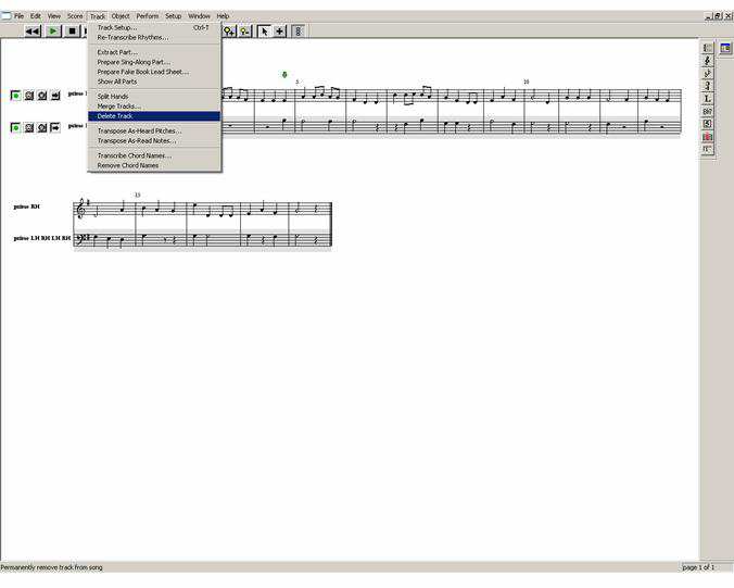
Download and run the program midinotate.exe, and open the merry christmas.mid file. You will be greeted with the screen below.
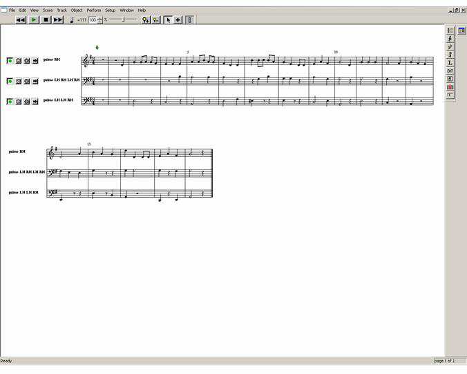
The above screen shot shows the merry christmas tune laid out as if it were sheet music. Each track will become our channels, however, in order to play successfully in our project, only single notes are allowed per channel. If multiple notes appear on a track then the track can be split using the SPLIT HAND option located in the TRACK menu. But sometimes this is not necessary, and simple editing will suffice. Take a look at the piece of music score shown below.
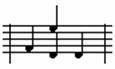
Notice how the two notes share the same track and the same location, one must be deleted, and it is up to you to decide which one.
Once you’re happy that you have a good clean three track piece of music, each track needs saving individually. I found the best way to do this is to temporarily delete the tracks that do not require saving.
For example, if we wish to save track 1, then delete tracks two and three, and save the midi file as MERRY CHRISTMAS 1.MID.
Repeat this for all three channels and you should now have three midi files, with each file containing a single track (channel). Midi files already split can be found along with the rest of programs for this project at the PROTON+ BASIC Users Page, named merry christmas 1.mid, merry christmas 2.mid and merry christmas 3.mid.
Now locate the program MIDI CONVERT.EXE, found with the above midi files, and place it and the midi files inside the EXTERNAL PROGRAMS folder located in the compiler’s INC folder. MIDI CONVERTER is a program written in Visual BASIC 6 that will convert the midi file containing the track data into a series of LDATA statements. You may need the VB6 runtime libraries for this program to operate. These can be downloaded from Microsoft’s web site at www.microsoft.com.
Once the programs are copied into the EXTERNAL PROGRAMS folder, open the compiler’s editor and choose the OPTIONS -> RUN menu.
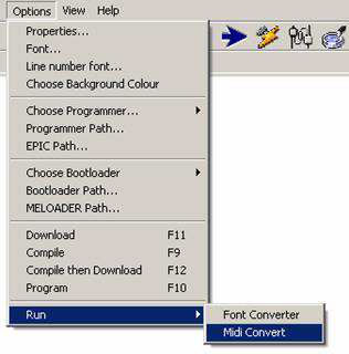
You will be presented with the midi converter window. Shown below.
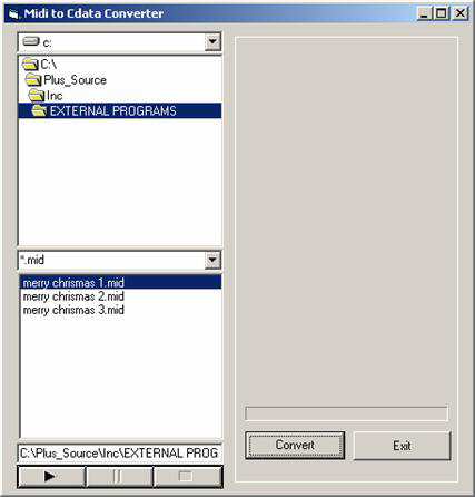
Navigate to where you’re EXTERNAL PROGRAMS folder is located and the three midi files will be listed. Click on the first file (merry christmas 1.mid) then click the CONVERT button. Once converted (which is accomplished extremely quickly), exit the window and the LDATA statements will be transferred to the compiler’s editor.
The list of LDATA statements should look something like the small snippet below.
TRACK_n:
          LDATA WORD 00270 , BYTE 062
          LDATA WORD 00324 , BYTE 067
          LDATA WORD 00378 , BYTE 067
          LDATA WORD 00405 , BYTE 069
          LDATA WORD 00432 , BYTE 067
          LDATA WORD 00459 , BYTE 066
Rename TRACK_n: to TRACK_1: and make sure the last LDATA statement contains all zeroes.
LDATA WORD 00000 , BYTE 000
If not, then add them to the list. Save this file as MERRY_TRACK_1.BAS.
Repeat the process for the remaining two midi files, renaming TRACK_n: to TRACK_2: and TRACK_3: respectively, not forgetting to save each file with an appropriate name.
Open the three new .BAS programs containing the LDATA statements, and copy and paste tracks two and three in to track one’s program. You should now have a single BASIC file containing all three tracks. Rename this file when saving to MERRY CHRISTMAS.BAS. This is now your music score.
Re-open the SIMPLE_TUNE.BAS program and change the line.
' Load the music score

      Include "TUNE_DATA.INC"
to
' Load the music score

      Include "MERRY CHRISTMAS.BAS"
Once the program is compiled and programmed into the PICmicro, you should hear the tune being played.
Although the separate track information allows a tune to be played, it’s very memory hungry because a lot of the ‘time to play the chime’ information is the same for each track. A better method of storing the music data would be a single LDATA statement containing the time to play, and which notes to play at that given time.
Included with the rest of the examples is a BASIC program named SINGLE_TABLE_MAKER.BAS to do just that. It combines the separate tracks into a series of single LDATA statements.
Load SINGLE_TABLE_MAKER.BAS, and place the separate track music data file’s name (created earlier) in the line:-
' Load the music score

          Include "MERRY CHRISTMAS.BAS"
Compile the program, then open the serial terminal set to 9600 baud. You will be prompted for a tempo value for the tune.
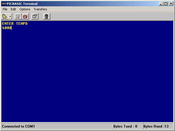
The tempo must be in microseconds (uS) and most tunes require values of approx 3000 to 5000 depending on the type of tune it is.
Once the ENTER key is pressed, the terminal’s screen will be filled with LDATA tables.
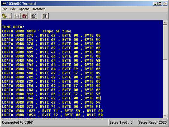
Select all the screen by pressing Ctrl-A, and copy the text by using Ctrl-C. Open a new BASIC text page in the editor and paste the new data tables by using Ctrl-V. Then save the new BASIC file created as MERRY.BAS.
The format for the new LDATA statements is: -
LDATA Time to Play a note , Channel 1 note , Channel 2 note , Channel 3 note
The tempo for the tune is stored at the very beginning of the list of LDATA statements.
In order to play the new music score format, you will need to load the program SINGLE_TABLE_PLAYER.BAS. Again, this can be found with the rest of the project examples.
The operation of this program is exactly the same as the previous ones, and if anything, it is a lot simpler in design.
By searching the internet over the past few weeks, I have managed to gather and convert a collection of festive tunes, and some not so festive. So the next program will play each tune sequentially.
Compile the program CHRISTMAS_JUKEBOX.BAS and use the same circuit as previously shown. The program will run through several tunes, playing each one in turn.
The program is essentially the same as the SINGLE_TABLE_PLAYER.BAS program, but instead of pointing to a single tune’s data, a separate LDATA statement holds the tunes to play.
Each tune’s LDATA list must be given a relevant name. For example, our merry christmas tune’s file now contains the label:
WISH_YOU_MERRY:
      LDATA WORD 4000 ' Tempo of tune
      LDATA WORD 270 , BYTE 62 , BYTE 00 , BYTE 00
      LDATA WORD 324 , BYTE 67 , BYTE 00 , BYTE 50
    LDATA WORD 378 , BYTE 67 , BYTE 00 , BYTE 00
Well, it’s now the 10th of December and I’ve run out of time and steam. I know this all sounds rather complicated, but once you’ve converted a few tunes successfully, it all fits into place and becomes much simpler.
I would like to take this opportunity to wish you a very merry Christmas and a prosperous new year from all the team at Crownhill, and I look forward to listening to some tunes that you convert.
Les Johnson.
You can download the original PDF file for printing and offline viewing, here
Crownhill's Proton Plus Compiler is a part of the Proton Development Suite - A suite of British-developed applications enabling fast development of PICmicro's using the PICBASIC Language.
Also mentioned in this project is the Proton Development Board. Why not have a look at the PDF Manual and see what it's capable of?
For more information on the Proton Development hardware and software, please visit www.picbasic.org