 |
 |
Based on the development of Lothar Stolz. and the discussion initiated by Roger on the forum end of last year( see here).
March 2005
 |
 |
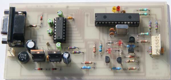
This project is not really a project but more an help to build a development tool. Surfing on the forum, I was interested by the discussion initiated by Roger about an ICD2 clone. It took me about 3 hours from reading the discussion to succeeding in the first connection to MPLAB. All components are common. No exotic ones.
This is the original schematic proposed by Lothar. I made only some small modifications. Some 0.1uf capacitors were added to make the project more robust. The power supply was also adapted. I added two spare places for Zener in order to be able to use a standard 7812 regulator for the VPP. By modifying the voltage level of the ground pin of the regulator, it becomes possible to adjust quite precisely the level of vpp. Personally, I added 2x1N4148 (adds 1.2 volt). The 2 leds on RB2 and RB3 were also added .
Board Print in TCI3.1 format (see How To concerning PCB design to get and use TCI freeware)
Just some comments.
 |
| R1 : 100K | U1 : 16F876 |
| R2 : 47K | U2 : MAX232 |
| R3, R4 : 22K | RG1 : 7812 |
| R5, R13 : 6.8K | RG2 : 7805 |
| R6, R14 : 2K2 | Q1 : 20Mhz |
| R7, R9, R10 : 330 | ZD1 : Zener 5.1 or 4.7 300ma |
| R8, R11, R15, R16 : 4K7 | ZD2, ZD3 : Optional zeners or 2x1N4148 to reach 13.2Volts |
| R12, R17 :1K | D1, D2 : OA85 or BAT54,... |
| R18, R19 : 470 | T1, T4 : BC 547B or BC 548B |
| T2, T3 : BC 557B or BC 558B | |
| BR1 : Bridge 40V 1.5A | |
| C1, C2 : 22pf | LD1,LD2,LD3 : LEDs |
| C3, C4, C5, C6 : 1uF or 10uF depending on the type of MAX232 used | |
| C7,C10,C11,C12 : 0.1uF | Connectors: DB9 female, connector 5 pins and connector 2 pins |
| C8, C9 : 100uF 25V | Supports for ICs |
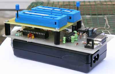
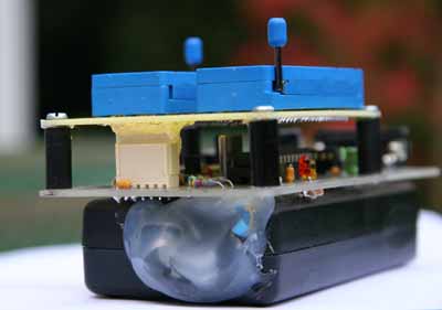
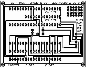
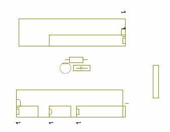
For those who want to use the ICD as a programmer, here is a small adaptator you can add on the main board. It adds two ZIP supports able to load 40,28,18 and 8 pins PICs. This was not develop for this specific project. This is why you will also find a 8 pins "place" able to support a EEPROM.
 |
 |
 |
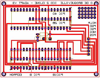 |
PCB can be found here as PDF and as TCI file
 |
Download MPASM from the Microchip site (free) and install it.
If you installed MPLAB with the default options, go to "C:\Program Files\Microchip\MPLAB IDE\ICD2" and retrieve the file "BL010101.hex"
Flash the 16F876 with this file
Connect the board to your PC and start MPLAB
Go to Programmer / Select Programmer / MPLAB ICD 2.
There is an alternative. You can flash the 16F876 with the file ICD661.HEX (in place of BL010101.hex). It seems to solve some issues some people encountered with BL010101.hex. It works fine at least with MPLAB 7.10
Possible errors:
If you get an error message concerning THE PORT, go to "settings" and change "communication" to the correct port.
If you get an error message saying that the port is already in use (what happened on my computer because of Microsoft Activesync with RS232 com port activated) do as follow: <CTRL><ALT><DEL>, go to "process" and locate "wcescomm.exe". Terminate this process. Or better, deactivate RS232 com port access in Activesync.
If none of the following errors occurred you will have the following error message, as the 16F876 has only the bootloader in memory.
 |
Go to "Programmer / Download ICD2 operating system" and do it. It will take a few moments. Be patient.
DONE.
ATTENTION: A small mistake in the text written on the copper side of the PCB indicates an inversion in the pins PGC and PGD. The pins of the target connector are as follow:
Olivier de Broqueville
March 2005
(Last update : 13/04/05)
Crownhill's Proton Plus Compiler is a part of the Proton Development Suite - A suite of British-developed applications enabling fast development of PICmicro's using the PICBASIC Language.
For more information on the Proton Development Suite, please visit www.picbasic.org
Please note that this project is published AS IS. No responsibility of the author in any cases can be invoqued. This project is for learning and entertainment purpose only. No vital application can be connected to it. As this project is published on a free and friendly base for the user site of PROTON +, it cannot be used in any condition for business or commercial use without explicit permission of the author.