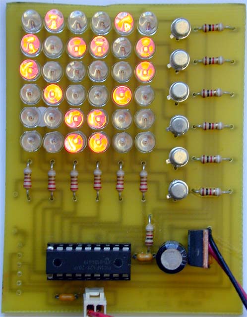

The idea of this project came from my youngest son. He was dreaming of a small tool able to write symbols or pictures on a screen. As a graphic LCD (even bought at Crownhill :) ) was too expensive (or too easy??), the solution adopted was to pilot a matrix of Leds. This way, with only some cheap transistors, common red Leds, and a 16F628 , the dream could become reality.

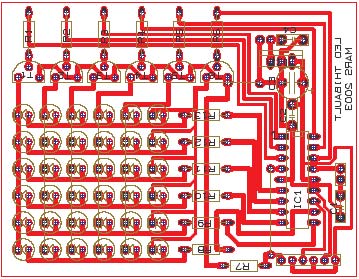
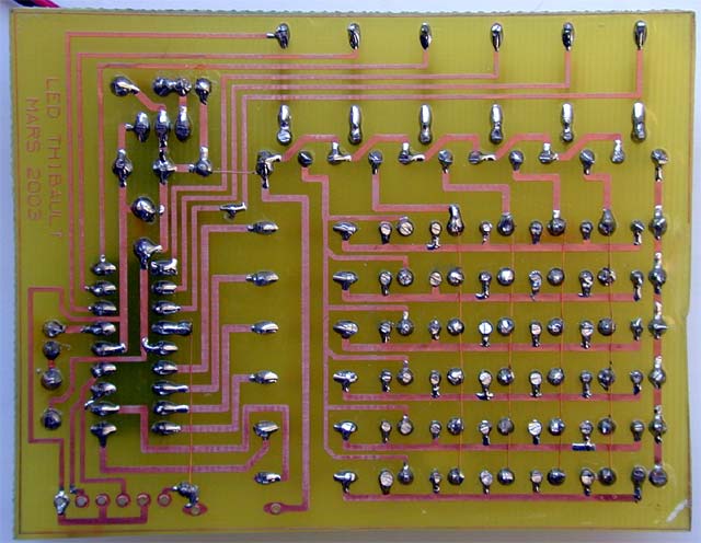
Board Print in TCI3.1 format (see How To concerning PCB design to get and use TCI freeware)
 |
 |
 |
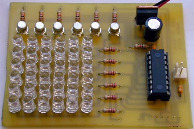 |
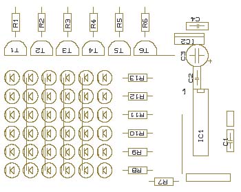
| R1-R2-R3-R4-R5-R6-R7 : 1K | IC1 : PIC 16F628 |
| R8-R9-R10-R11-R12-R13 : 220R | IC2 : 7805 |
| T1-T2-T3-T4-T5-T6 : 2N2222A | |
| C1-C2-C4 : 100nF | |
| C3 : 470 uF 16V | L1 to L36 : 5mm RED LEDs (or the color you want) |
| POT 1 : 10K LIN | 1 x 9V battery connector |
The program is very short. Basically, it
Reads the value of the pot. This will determine the speed of the picture change. The refresh of each picture is determined by small delays inside the 'picture' loop.
FREQ= POT V,64
IF FREQ<2 THEN FREQ=2
Reads data in a data file. Each data will trigger the appropriate LEDs of each column (+ of LEDS). PORTB decides which LED will be on.
HIGH L1:LOW PORTB
PORTB=LREAD AFFI+(IMG*6)
DELAYMS ps
Scan all 6 columns by setting each appropriate line (and associated transistor) in order to trigger each row (- of LEDs) this is the way the LED matrix is multiplexed.
The pictures are stored in the AFF file. The structure of this file is easy to understand: Each data is the PORTB 'BYTE' which determines which LED of a specific LINE have to be ON. A loop will scan all 6 lines (by triggering appropriate pins of PORTA. PORTA will, in turn, command NPN transistors (here 2N2222 but nearly all common low signals NPN could be used). This is the way the multiplexing is implemented.
To define pictures, a AFF file has to be build. As the program was written for a 9 year old kid, some assistance was needed... :) This is why a VB program was added.
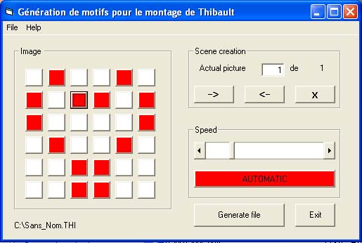 |
This application is written in Visual Basic 6 SP5. It needs the VB6sp5 runtime. If you do not have it, you can find it HERE
There are basically no adjustments. It has to work immediately
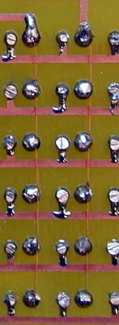
The only small difficulty is the 6 horizontal connections of the LEDs: This is a zoom of how it was done using isolated wire:
 |
Developed by Olivier de Broqueville in March 2003
(Last edition 7/12/03)
Crownhill's Proton Plus Compiler is a part of the Proton Development Suite - A suite of British-developed applications enabling fast development of PICmicro's using the PICBASIC Language.
For more information on the Proton Development Suite, please visit www.picbasic.org
Please note that this project is published AS IS. No responsibility of the author in any cases can be invoqued. This project is for learning and entertainment purpose only. No vital application can be connected to it. As this project is published on a free and friendly base for the user site of PROTON +, it cannot be used in any condition for business or commercial use without explicit permission of the author.