Ultrasonic
Range Finding.
First Principles.
Measurement of relatively
short distances has traditionally been carried out using a tape measure made of
wood, metal or paper etc. However, in recent years another method of measuring
distances has become popular, that of using sound, ultrasonic sound to be exact.
The word Ultrasonic
means ‘above sound’, the above part referring to above the human hearing range
which is approx 300Hz to 14KHz. Therefore any frequency that is above the human
hearing wavelength and below the low frequency RF wavelength may be considered
as ultrasonic or ‘ultrasound’.
Nature has used sound
as a method of distance sensing for tens of millions of years without a single semiconductor.
Bats, Dolphins and to a lesser extent, a few fish, use ultrasound as a form of
sight, allowing them to see where they’re going and to catch prey on the
darkest night or in the muddiest water. And in the dolphins case, it can also
increase the amplitude of its ultrasonic transmitter, and use it as a form of
stun gun. This has also recently been found true for some breeds of Bat.
Even when ultrasound
is not used as a sixth sense, many mammals have a much higher upper limit to
their hearing, so ultrasound to them could start as high as 20KHz. This is the
principle behind the dog whistle. When blown, we humans do not hear the high frequency
vibrations, but a dog hears it as if it were a referee’s whistle. However, I’m
straying from our objective a little, so lets get back on track.
Ultrasonic ranging is
performed by transmitting a pulse of high frequency sound, then counting how
long it takes for its echo to be detected. Because sound through a given medium
(liquid or air) is a known quantity, it can be considered a constant, the
length of time taken between the transmitted pulse and the received echo can be
converted into distance. This is called Time of Flight (TOF).
The Speed of Sound.
For an ideal gas; the
speed of sound is mainly a function of temperature. Luckily for us on earth, the
behaviour of air is very close to that of an ideal gas unless the temperature
or pressure is very high or very low compared to standard sea level conditions,
or my office. This is what the text books tell us, and I have no reason to
doubt it.
Therefore the speed of
sound c for an ideal gas, in our case
air, is: -
![]()
![]() c
= g R T
c
= g R T
where
c = Speed of sound in metres per second
g = Ratio of specific heats.
For dry air g = 1.4 (non-dimensional)
R = Gas constant. For dry air,
R = 286.9 N×m/(kg×K)
T = Absolute temperature
(Kelvin), where 0°C = 273.16 K
For example, the speed
of sound at room temperature (22°C, 71.6°F) is: -
![]()
![]() c
= 1.4 * (22 + 273.16) * 286.9 =
344.31 metres per second
c
= 1.4 * (22 + 273.16) * 286.9 =
344.31 metres per second
The speed of sound
also depends on the type of gas. Suppose we want to operate a sonar range finder
on Mars! How can we determine the speed of sound there?
The atmosphere on Mars
is approximately 95.3 % carbon dioxide (CO2). For CO2,
the ratio of specific heat g equals 1.29, and the gas constant R equals 188.9 N×m/(kg×K). Assuming a pure CO2 atmosphere,
the speed of sound at room temperature,
which on Mars is considered a hot day, is as follows: -
![]()
![]() c
= 1.29 * (295.16) * 188.9 =
268 metres per second
c
= 1.29 * (295.16) * 188.9 =
268 metres per second
Notice that neither
pressure nor density appear in this equation. Even though surface pressure on
Mars is only a tiny fraction of that on Earth, the low pressure has essentially
no effect on the speed of sound in a gas.
Aptly named ‘Echo
Ranging’ or SONAR does not exclusively require ultrasound, ‘during the war’,
submarine detection was carried out by transmitting a relatively low frequency,
but high amplitude ‘ping’ in the order of 2KHz. Any submarines in the proximity
of the sound wave will reflect a portion of the sound back to the receiver. By
moving the transmit/receive device named a transducer, the submarine’s bearing
and approximate distance could be ascertained. However, as electronics gained
more sophistication, it became possible to transmit and receive higher frequency
sound. Coupled to that, the discovery that higher frequency sound had more
directional properties and was able to carry more energy, produced the now very
sophisticated fish finding SONAR carried by virtually all fishing vessels. And
allows sunken ship wrecks to be pinpointed with impressive accuracy.
Uses for ultrasonic
sound are constantly increasing and now number in their hundreds; ranging from
medical to metallurgic, but even though the technology has moved forward, the
principle stays the same.
Practical Circuit Design.
Of course, we cannot
possibly hope to create anything as sophisticated as a side scan SONAR used for
wreck location, but using a handful of common components and a little BASIC code,
we can add object detection and distance measurement to a future project simply
and efficiently.

For all our
experiments, we’ll be using readily available 40KHz ultrasonic transducers.
These come as a pair with one being optimised for transmission and the other for
reception. An illustration of the transducers used in the experiments is shown
to the right.
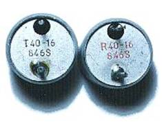
It is important to identify
which is which as any subsequent results may suffer. The transducers used were
clearly marked on the underside, but I am unsure if this is a common practice
among these types of transducers.
As their name implies,
these devices operate at a frequency of 40KHz, which is nearly three times
higher than the best human hearing, so we don’t have to worry about noise
pollution. This frequency is also above the range of dogs and cats hearing, so
you won’t harass your pets.
 The
circuit for our range finding experiments is shown below.
The
circuit for our range finding experiments is shown below.
As you can see, the
circuit is remarkably simple, consisting of two ICs (U1a and U1b are in the
same 8-pin package) and a handful of common value discrete components.
Receiver circuit explanation.
The signal picked up
from the ultrasonic transducer is extremely small, so in order to be of any use
it needs quite a significant amount of amplification. ICs U1a and U1b form a
standard high gain preamplifier, with U1a having a gain of 10 set by resistors
R1 and R2, and U1b having a gain of 100 set by resistors R4 and R7. So altogether
they form a pre-amp with a gain of 1000 (10 * 100). Remember that both these
ICs are enclosed in the same 8-pin package.
There is no need for a
coupling capacitor for the input of U1a, as the transducer can be thought of as
a type of capacitor, therefore it does not present a resistive load.
Resistors R5 and R6
together with capacitor C2 form a potential divider that supplies the op-amps
with half the voltage rail. This commonly named ‘floating ground’ eliminates
the need for a negative supply that usually frightens people away from using
op-amps.
The output of U1b is
now sufficiently large enough to be useful, but is not suitable for interfacing
directly to the PICmicro microcontroller. The PICmicro expects a clean high or
low on its IO pin, but the output of the op-amp is an amplified AC signal with
a midpoint voltage of approximately 2.5 Volts. This is were the clever part of
the circuit comes in. In order to convert the AC signal into discernable highs
and lows, we use an LM393 comparator (U2).
A comparator works by
comparing the voltage on its two inputs, if the +ve input is more positive than
the -ve input, the output will be high, but if the +ve input is more negative
than the -ve input, the output will be low. Without any input signal to the pre-amplifier,
the output of U1b will be a steady DC voltage of approx 2.5 Volts. This is fed
directly to the +ve input of the LM393 comparator. The same voltage from U1b’s
output is also fed through VR1 and R8 to the -ve input of the comparator, however
R9 connected to ground makes this network function as a potential divider thus reducing
the voltage. So the voltage on the -ve input is slightly lower than the +ve
input, and the output is high, this is the 'no obstacle state'. When an echo is
received, an amplified version of the signal appears on the output of U1b and
is fed to the +ve input of the comparator which now goes both higher and lower
than before as the AC signal is super-imposed on the original DC voltage. However,
the -ve input is fed through the resistor network VR1, R8 and R9, and has C3 connected
to ground, this makes a low-pass filter, removing all the signal and maintaining
the same DC voltage as before. So, if the received signal on the +ve input
should go lower than the voltage on the -ve input the comparator output will go
low, and the output from the comparator will be a series of negative going
pulses just right for connecting to the PICmicro.
By adjusting VR1, the
voltage difference varies between the +ve and -ve inputs of the comparator and
makes it more or less sensitive. This overcomes any problems from the rather unsophisticated
op-amp pre-amplifiers, and makes the circuit somewhat self adjusting as it will
automatically compensate for any gain variations.
Transmitter circuit explanation.
The most involved part
of the range finder is the receiver, but transmitting the 40KHz signal is just
as important but very straightforward as the PICmicro does most of the work for
us.
We need to transmit as
large a signal as possible in order to carry enough energy to have a portion of
it reflected back to the receiver. To do this, we drive the transducer in a simple
form of push-pull setup. This ensures that the transducer is operating with
both cycles of the 40KHz wave. The illustration below shows this: -

The waveform entering
the base of the transistor is our 40KHz signal produced by the PICmicro. This
is then amplified by the transistor and produces a two phase output on its
emitter and collector. When one is pushing, the other is pulling. i.e. out of
phase by 180°. We are still only driving the transducer at 5 volts, but the above
method imitates a drive of nearly double that. This arrangement will give us an
effective range of a little over 2 metres, which is more than enough to
experiment with, and indeed enough for most applications.
Both the circuit and
the software are designed around the Crownhill PROTON Development board. This
offers a comfortable an efficient method of developing a PICmicro project. However,
this is not mandatory and the circuit can be built using any medium.
The PROTON Development
board has a PIC16F877 PICmicro device at its heart, and attaches to a 2*16 line
Alphanumeric LCD which we’ll use to display the results. It also has a
solderless breadboard area where we can build our circuit. The layout of the
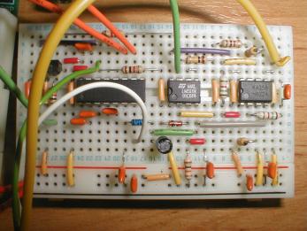
ultrasonic range finder on the solderless breadboard area is shown overleaf.
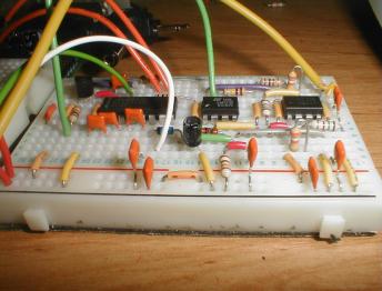
It’s surprising what
can be squeezed on to the small breadboard with a little care, the secret is
the Wire Jumper kit also available from Crownhill. This offers both tidiness
and repeatability as each wire length is colour coded differently. Anyway, a
different angle photograph of the same board layout is shown below in order to
clarify any obscured components in the picture above.

Transducer mounting.
For obvious reasons,
both the transmit and receive transducers should be facing in the same direction.
But there is another phenomena that can cause potential disaster for your
experiment, that of ‘ringing’.
Each time the
transmitter sends out a 40KHz ping, the receiver physically vibrates (rings)
in sympathy. This ringing can cause the receiver’s sensitive amplifiers to see
a false reflection immediately after the ping, especially if the sensitivity
control (VR1) is set high. In order to help alleviate this problem, both the
transmitter and receiver transducers must be padded in order to isolate them somewhat
from the medium on which they are both attached. i.e. the PCB. This was
accomplished in the prototype by placing a piece of felt on the bottom of the
transducers where the connecting wires protrude. The illustration below shows
the prototype’s arrangement.
Because we’re not
transmitting a very powerful signal from the send transducer, the ringing
effect if not too much of a problem, but it is important to be aware of the phenomena.
The receive transducer
should be connected to the pre-amplifier’s input using a single core screened
cable (small diameter microphone cable). After all, the pre-amplifier’s input
is of a high impedance, and the transducer is a form of microphone, so the same
precautions should be carried out as if we were dealing with an audio signal. This
is especially important if, like the prototype, the transducer setup is a few
inches away from the receiver’s circuit. If the transducers are mounted on the
same PCB as the receiver, then this precaution is obviously eliminated, but you
must still treat it as if it were audio, and keep the circuit away from strong
AC signals, such as transformers, television sets etc. If strong AC signals
enter the pre-amplifier, then false readings may occur as they swamp the tiny
signals produced by the transducer.
The transmit
transducer’s hook-up is not as
critical, so standard multi-core wire can be used.
Range Finding Software.
Now that we know how
the circuit works, we can look at the PICmicro BASIC code that brings everything
together and produces a usable range reading on the LCD. The full listing for
the program is shown below.
'
' Ultrasonic range finding
' For use with the two op-amps and an LM393 comparator using a single power
supply
' The program uses TIMER1 as an accurate duration counter.
' With this code, a resolution down to 1 inch can be realised.
'
' Written by Les Johnson for use with the PROTON+ Compiler Version 2.1 onwards.
'
'
Include "PROTON_4.INC" ' Use the PROTON
Development board with a 4MHz xtal
Device = 16F871 ' Fake a smaller device for a small routine
WARNINGS = OFF '
Disable warning messages
Symbol ECHO = PORTB.0 ' Echo signals from comparator
Symbol TX1 = PORTB.4 ' 40KHz signal pin
Symbol TIMER1 = TMR1L.WORD ' Create a 16-bit variable out of TMR1L/TMR1H
Symbol TMR1ON = T1CON.0 ' TIMER1 Enable/Disable
Symbol TMR1IF = PIR1.0 ' TIMER1 overflow flag
Dim PING_LOOP as Byte ' PING Loop counter
Dim PULSE_LENGTH as Word ' TOF (Time Of Flight) value
'---------------------------------------------------------------------------------
' Program starts here
Delayms 500 ' Wait for PICmicro to stabilise
INTCON = 0 ' Make sure all interrupts are OFF
T1CON = %00000001 '
Enable Timer1 with a prescaler of 1:1
TRISB = %00000001
'
Set ECHO pin as input, all others as outputs
Cls ' Clear the LCD
Goto MAIN_PROGRAM_LOOP ' Jump over the PING subroutine
'---------------------------------------------------------------------------------
' The PING routine generates a 40khz burst of 8 cycles.
PING:
PING_LOOP = 8 ' Number of cycles in ping
PING1:
Set TX1 ' 1st half of
cycle
Delayus 10 ' Create a delay of 10uS
Clear TX1 ' 2nd half of cycle
Delayus 9 ' Create a delay of 9uS
Djnz PING_LOOP,PING1 ' Special mnemonic to form a fast loop
Return
'---------------------------------------------------------------------------------
' The main program loop starts here
MAIN_PROGRAM_LOOP:
While 1 = 1 ' Create an infinite loop
TMR1ON
= 1 ' Enable TIMER1
Delayms 100 ' Delay 100 ms between samples
TMR1IF
= 0 ' Clear TIMER1 overflow
Gosub PING '
Transmit a 40KHz pulse
TIMER1
= 0 '
Reset TIMER1 before entering the loop
Repeat ' Loop until TIMER1 overflows
If ECHO = 0 Then ' Capture TIMER1 if a LOW on ECHO pin detected
TMR1ON
= 0 ' Disable TIMER1 at this point
PULSE_LENGTH = TIMER1 ' Store the value of TIMER1
Break ' Exit the loop
Endif
PULSE_LENGTH = 0 ' If we reached here then Out of Range
Until TMR1IF = 1 ' Timeout if TIMER1 overflows
If PULSE_LENGTH = 0 Then ' Did we reach the end of the loop ?
Print at 1,1,"OUT OF RANGE " '
Yes. So Display text if out of range
Else ' Otherwise...
'
Display distance in inches
Print at 1,1,"DIST = ",DEC
PULSE_LENGTH / 146,34," "
Endif
Wend
Software explanation.
The BASIC program that
ties everything together is surprisingly simple in its operation, but has been
carefully crafted to allow more than enough accuracy.
The program is centred
around one of the PICmicro’s hardware timers. TIMER1, or TMR1 to give it its
official name, is a 16-bit timer that, once enabled, will start counting on
every instruction cycle (FOSC/4). When the timer overflows. i.e.
reaches a count of 65536, a flag will be set (TMR1IF) and the timer will start
counting from 0 onwards again. TIMER1 can be both read and written to, thus
allowing a precise measurement of time to be measured. TIMER1 has two modes of
operation, counter or timer, we’re using it as a timer in this program.
At this point it may
be a good idea to have the PIC16F877’s datasheet at hand, which can be
downloaded, free of charge, from www.microchip.com.
Another great free download from Microchip is the midrange reference manual,
which is packed full of useful information relating to all aspects of the
PICmicro’s architecture and operation, including detailed information relating
to the PICmicro’s several timers.
The program starts by
enabling TIMER1 and assigning a 1:1 prescaler to it, this means that the timer
will increment on every instruction cycle. Different prescaler ratios can also
be attached to TIMER1 allowing it to increment on every 2, 4, 8, 16, 32, 64 or
128 instruction cycles. However, in our application, we need microsecond
timing, so a 1:1 ratio is perfect.
After clearing the
TIMER1 overflow flag (TMR1IF), the program then calls the PING subroutine which
transmits a 40KHz signal 8 times from PORTB.4. Timing within the PING subroutine
is deliberately accurate, as the amount of cycles taken by each instruction dictates
the frequency and duration of the output signal.
Once the ping has been
transmitted from the transducer, TIMER1 is cleared and a loop is formed to
detect the returning echo. The echo pin (PORTB.0) will be pulled low if a
signal was detected, and TIMER1 will be halted and its value transferred to the
variable PULSE_LENGTH, then the loop will be exited using a BREAK command. If an echo signal is not
detected within the full range of TIMER1 (65535), the loop will be exited
anyway by checking the TIMER1 overflow flag, which will clear the variable
PULSE_LENGTH.
We have now captured
the Time of Flight value from the transmitted ping to it’s reception (if any).
So we can convert the time into distance using some simple experimentation and
a little arithmetic.
We know from the
earlier discussion that the speed of sound here on earth (in my office anyway)
is 344 Metres per Second, or 3440 centimetres per second, and we know how long
in microseconds it took for the echo to be received, so by dividing the time
taken; by the speed of sound, we can come up with the distance in centimetres
to the target object. Well not quite… we do have some overheads to take into
account such as the duration of the initial 40KHz ping, sound propagation, and
latency caused by software and hardware etc. This is where some experimentation
comes in.
As an example, the
distance from the top of the transducer pair sitting on my bench to the ceiling
is exactly 150cm or 59 inches, as measured using an old fashioned tape measure.
The raw value produced in PULSE_LENGTH (derived from TIMER1) is 8642. It
actually varies from 8642 to 8666 but this will be ironed out with the
division. This value is a close approximation of how many microseconds it took
for the round trip of the 40KHz ping plus the overheads mentioned above. The
setup I used is shown below.

Dividing the raw
distance of 8642 by 150 gives a value of 57.6, so without using floating point,
our calculation to convert to centimetres is a simple division by 58: -
PULSE_LENGTH / 58
57.6 is closer to 58
than it is to 57, so a division by the closest integer is sufficient with the integer
math that we’re using.
To calculate the value
in inches, I used the same principle. I divided the raw distance value
contained in PULSE_LENGTH (8642) by 59, which is the imperial representation of
150 centimetres. This gave me a value of 146.4, so if we divide by its closest
integer of 146, we’ll get the distance measured in good old inches.
PULSE_LENGTH / 146
As you can tell, I’m
not a mathematician or I would have calculated the overheads instead of
experimenting, but isn’t that the whole point of this discussion, and anyway where’s
the fun in knowing beforehand what’s going to happen.
The relevant distance
is displayed on the LCD using the standard PRINT
command, only if the value of PULSE_LENGTH is greater than zero. If
PULSE_LENGTH is equal to zero then this means that TIMER1 overflowed because no
echo was received, and the text “OUT OF RANGE” is displayed.
Clarifying the results.
Our simple receiving
circuit does not have sophisticated filtering or gain controls, so the results
can be rather erratic at times. However, this is true of most simple ultrasonic
range systems, as sound can be reflected and bounced around by many objects in
the vicinity of the initial ping. One way of alleviating this is to use a
process named MEDIAN filtering, Median meaning Middle.
A median filter simply
takes the middle value of a sorted sample range. Because the range of samples
is sorted in either ascending or descending order, any erroneous results should
be on the extremities of the samples, and the average value should be somewhere
in the middle. For example, suppose we have 7 samples: -
149, 150, 1, 151, 150,
0, 150
A simple average (Addition
of all values divided by the amount of values) of these samples would produce a
value of 107, which is totally wrong as the average value is clearly between
149 and 151, and is actually 150. It’s the values 0 and 1 that have clouded the
result.
To median filter the
same 7 samples involves using a straightforward bubble sort algorithm to
arrange the values in ascending order.
0, 1, 149, 150, 150,
150, 151
Now if we take the
fourth (middle) value in the list, we get the average of 150.
Of course, this method
isn’t perfect, and it does rely on the amount of samples taken. For example, if
only 3 samples were taken, there’s a good chance that the average value would
not be the middle value when sorted, but if 15 samples, or more, were taken,
there’s a very good chance that all the erroneous values will be pushed to the
outskirts of the samples and the true result will lie somewhere in the middle.
As mentioned above,
median filtering relies heavily on a bubble sort algorithm, and a simple bubble
sort demonstration program written in PROTON+ BASIC is listed below.
' Bubble sort
Demonstration
Include "PROTON_4.INC"
Symbol SAMPLES_TO_TAKE = 7 ' The
amount of samples to take
Dim SAMPLE[SAMPLES_TO_TAKE] as Byte ' Create an array to hold the samples
Dim SWAPTMP as Byte ' Temporary variable for swapping
Dim INDEX as Byte ' Holds the position in the sort
Dim SWAP_OCCURED as Bit ' Indicates if the sort is complete
Delayms 200 ' Wait for
the PICmicro to stabilise
Clear ' Clear all RAM before we start
Cls ' Clear the LCD
STR SAMPLE = 149, 150, 1, 151,
150, 0, 150 ' Load the array with values
Gosub BUBBLE_SORT ' Do the bubble sort
' Display the sorted list
Print at 1,1,Dec SAMPLE[0],":",Dec SAMPLE[1],":",Dec
SAMPLE[2],":",Dec
SAMPLE[3]
Print at 2,1,Dec SAMPLE[4],":",Dec SAMPLE[5],":",Dec
SAMPLE[6]
Stop
'--------------------------------------------------------------------
' This subroutine implements a
technique called "bubble sort."
BUBBLE_SORT:
Repeat
SWAP_OCCURED = 0 ' Clear flag that indicates a swap.
INDEX = 0
Repeat ' For each cell
of the array...
If SAMPLE[INDEX] > SAMPLE[INDEX + 1]
Then '
move larger values up.
SWAPTMP = SAMPLE[INDEX] ' ..by
swapping them.
SAMPLE[INDEX] = SAMPLE[INDEX + 1]
SAMPLE[INDEX + 1] = SWAPTMP
SWAP_OCCURED = 1 ' Set bit if swap occurred.
Endif
Inc INDEX
Until INDEX = SAMPLES_TO_TAKE ' Check next cell
of the array.
Until SWAP_OCCURED = 0 ' Keep
sorting until no more swaps.
Return
The idea behind the
bubble sort subroutine is quite straightforward.. compare adjacent bytes in the
array. i.e. SAMPLE[0] and SAMPLE[1]. If
the value stored in SAMPLE[0] is less than or equals that in SAMPLE[1] then do
nothing. Otherwise, swap the values so
that SAMPLE[0] gets the contents of SAMPLE[1],
and vice-versa. Keep doing this with each pair of values in the array,
and the larger values will migrate toward the higher index values. Repeated
passes through the array will completely sort it. The routine is finished when
it makes a loop through the array without swapping any pairs.
We can now incorporate
the BUBBLE_SORT subroutine in our original range finding program, but we need
to make some changes in order to take nine range samples instead of the
original single sample. The listing for the new program is shown below.
'
' Ultrasonic range finding
'
' For use with the two op-amps and an LM393 comparator using a single power
supply
' The program uses TIMER1 as an accurate duration counter
' and a
MEDIAN filter to give a more reliable reading
'
' Written by Les Johnson for use with the PROTON+ Compiler Version 2.1 onwards.
'
'
Include "PROTON_4.INC" ' Use the PROTON Development board with a 4MHz xtal
Device = 16F871 ' Fake a smaller device for a small routine
WARNINGS = OFF ' Disable
warning messages
Symbol ECHO = PORTB.0 ' Echo signals from comparator
Symbol TX1 = PORTB.4 ' 40KHz signal pin
Symbol TIMER1 = TMR1L.WORD ' Create a 16-bit variable out of
TMR1L/TMR1H
Symbol TMR1ON = T1CON.0 ' TIMER1 Enable/Disable
Symbol TMR1IF = PIR1.0 ' TIMER1 overflow flag
Symbol SAMPLES_TO_TAKE = 9 ' The
amount of range samples to take
Dim SAMPLES[SAMPLES_TO_TAKE] as Byte ' Create an array to hold the range samples
Dim SAMPLE_COUNT as Byte
Dim PING_LOOP as Byte ' PING Loop counter
Dim PULSE_LENGTH as Word ' TOF (Time Of Flight) value
Dim SWAPTMP as Word
Dim INDEX as Byte
Dim SWAP_OCCURED as Bit
Dim MEDIAN as Word
'---------------------------------------------------------------------------------
' Program starts here
Delayms 500 ' Wait for PICmicro to stabilise
INTCON = 0 ' Make sure all interrupts are OFF
T1CON = %00000001 ' Enable Timer1 with a prescaler of 1:1
TRISB = %00000001 ' Set ECHO pin as input, all others as outputs
Cls ' Clear the LCD
Goto MAIN_PROGRAM_LOOP ' Jump over the subroutine
'---------------------------------------------------------------------------------
' The PING routine generates a 40khz burst of 8 cycles.
PING:
PING_LOOP = 8 ' Number of cycles in burst
PING1:
Set TX1 ' 1st half of
cycle
Delayus 10 ' Create a delay for 10uS
Clear TX1 ' 2nd half of cycle
Delayus 9 ' Create a delay
for 9uS
Djnz PING_LOOP,PING1 ' Special mnemonic to form a fast loop
Return
'---------------------------------------------------------------------------------
' Create a MEDIAN filter to make an educated guess as to what is the true
reading
' from the sample readings taken.
' The routine below is a BUBBLE SORT, that arranges all the samples in
ascending
' order
within the array SAMPLES.
' The middle sample is then extracted.
' This should eliminate spurious readings from the edges.
MEDIAN_FILTER:
Repeat
SWAP_OCCURED = 0 ' Clear flag that indicates swap.
INDEX = 0
Repeat ' For each cell
of the array...
If SAMPLES[INDEX] >
SAMPLES[INDEX + 1] Then ' Move larger
values up.
SWAPTMP = SAMPLES[INDEX] ' ..by swapping
them.
SAMPLES[INDEX] = SAMPLES[INDEX + 1]
SAMPLES[INDEX + 1] = SWAPTMP
SWAP_OCCURED = 1 ' Set bit if swap occurred.
Endif
Inc INDEX
Until INDEX = SAMPLES_TO_TAKE ' Check out next
cell of the array.
Until SWAP_OCCURED = 0 ' Keep sorting until no more swaps.
PULSE_LENGTH = SAMPLES[4] ' Extract
the middle sample's value
Return
'---------------------------------------------------------------------------------
' Take a range reading
GET_RANGE:
Delayms 20 ' Delay 20 ms between samples
TMR1ON = 1 ' Enable TIMER1
TMR1IF = 0 ' Clear TIMER1 overflow
Gosub PING ' Transmit a 40KHz pulse
TIMER1 = 0 ' Reset TIMER1 before entering the loop
Repeat ' Loop until TIMER1 overflows
If ECHO = 0 Then ' Exit if a LOW on the ECHO
pin is detected
TMR1ON = 0 ' Disable TIMER1 at this point
PULSE_LENGTH = TIMER1 ' Store the value of TIMER1
Break ' Exit the loop
Endif
PULSE_LENGTH = 0 ' If we reached here then Out of Range
Until TMR1IF = 1 ' Timeout if TIMER1 overflowed
Return
'---------------------------------------------------------------------------------
' The main program loop starts here
MAIN_PROGRAM_LOOP:
While 1 = 1 ' Create an infinite loop
SAMPLE_COUNT = 0
Repeat ' Create a loop for all the sample readings
Gosub GET_RANGE ' Go get a range
SAMPLES[SAMPLE_COUNT] = PULSE_LENGTH /
58 ' Convert into cm and store it
Inc SAMPLE_COUNT
Until SAMPLE_COUNT = SAMPLES_TO_TAKE ' Loop until all
samples taken
Gosub MEDIAN_FILTER ' Perform a median filter on the samples
If PULSE_LENGTH = 0 Then ' Did we reach
the end of the loop ?
Print at 1,1,"NOTHING IN RANGE" ' Yes. So
Display text if out of range
Else ' Otherwise...
' Display distance in centimetres
Print at 1,1,"DIST =
",DEC PULSE_LENGTH," cm "
Endif
Wend
The range finding part
of the program hasn’t really changed a great deal, it’s simply now called as a
subroutine, aptly named GET_RANGE.
The main part of the
program forms a nine cycle loop in order to fill the array with samples at 20ms
intervals. Once all the samples are taken, the MEDIAN_FILTER subroutine is
called to sort the array and extract the middle value. This is then displayed
on the LCD.
There is another
method we could use that still involves the median filter, that of averaging.
This entails adding the middle three of the nine samples taken, then dividing
them by the amount of additions, in our case three.
This can be
implemented in our program with a single line change. Within the MEDIAN_FILTER
subroutine, change the line: -
PULSE_LENGTH = SAMPLES[4]
to
PULSE_LENGTH =
(SAMPLES[3] + SAMPLES[4] +
SAMPLES[5]) / 3
This method is better
performed with more samples, but more samples means a larger delay between
range findings. This is only ascertainable with the type of project that it’s
intended for, and I’ll leave it up to you whether or not you implement it.
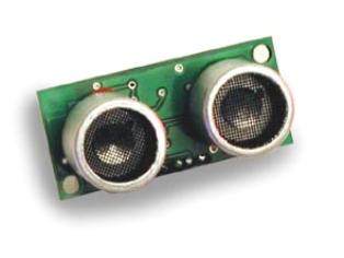
Ready made units.
If you don’t have the
resources or the time to build the ultrasonic range finder from scratch, then
there are a couple of alternatives. The people at Daventech have created two ultrasonic
range finding modules that are very easy to interface with, and produce surprisingly
good results. The SRF04 is the more
basic of the two modules and uses a simple interface method but requires more
code in order to obtain useful results. The SRF08 on the other hand, is packed full of features that will keep
any twiddler happy for hours. It uses a more involved interface method but
requires very little code to product remarkably accurate results.
Interfacing with the SRF04.
The SRF04 ultrasonic
range finder is a small PCB measuring only 43mm by 20mm. It has two transducers
attached, one for transmit and one for receive. The illustrations below show
the front and rear views of the SRF04.

Connections to the
SRF04 are via four of its five PCB pads shown below.
As far as I can tell,
there is no polarity protection or voltage regulation on the PCB, so the SRF04
must be supplied with no more than 5 Volts, and the correct polarity must be observed
otherwise damage ‘will’ occur.
The TRIGGER pin causes
the SRF04 to take a range reading when it is cycled high to low, and must be in
the high state for no less than 10us.
The ECHO pin will
remain in the high state until an echo is detected. Measuring the length of
time that the pin stays high will give us a measure of time in microseconds
that we can convert into distance. In order to convert the returned pulse
length into centimetres, we need to divide by 36, and to convert to inches we divide
by 73.
The full listing for a
program to control the SRF04 with the PROTON+ BASIC compiler is shown below.
The TRIGGER pin should be connected to PORTB.1 of the PICmicro, and the ECHO
pin should be connected to PORTB.0.
Include "PROTON_20.INC" ' Use the PROTON board with a 20MHz xtal
Symbol TRIGGER = PORTB.1 ' Define pin for Trigger pulse
Symbol ECHO = PORTB.0 ' Define pin for
Echo pulse
Dim RANGE as Word
' 16 bit variable for Range
Delayms 200 ' Wait for PICmicro to stabilise
Cls ' Clear the LCD
While 1 = 1
Pulsout TRIGGER,15,HIGH ' Produce a 15us high to low pulse
RANGE = Pulsin ECHO,1 ' Measures the range in uS
Delayms 10 ' 10ms recharge period after ranging completes
RANGE = RANGE / 62
' Use 62 for cm or 149 for inches
Print at 1,1,"RANGE = ", Dec Range," cm "
Wend
Notice that were using
a 20MHz crystal. This is because the resolution of the PULSIN command is simply not good enough for accurate results if a
lower frequency oscillator is used. The resolution of PULSIN with a 20MHz crystal is 2us, which is more than enough for
good accuracy.
Because we have a 2
microsecond resolution, the division to convert into centimetres or inches has
to be doubled. So to convert to centimetres, we divide the returning pulse
length by 62, and to convert to inches, we divide the pulse length by 146.
It is possible to
break the returned pulse length into fractions of a centimetre or inch, but
this is asking a little too much from ultrasonic range finding in general,
never mind the little SRF04. However, by utilising the Median filter subroutine
discussed earlier, the results from the SRF04 can be made extremely stable, and
very accurate.
There’s not a lot else
I can say about this module that isn’t shown in the demonstration program
above. It really is that simple to use!
One thing that I found
really useful was the fact that on the Daventech web site www.robot-electronics.co.uk ,
you can find the circuit diagram of the SRF04. And with a little modification,
the range finder programs discussed earlier will work perfectly with it.
And to prove it, shown
below are some pictures of the circuit for the SRF04 built on the PROTON
development board’s solderless breadboard area.
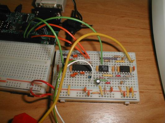
OK, so it’s not
actually built on the PROTON development board’s solderless area, but the
breadboard used is identical.
For ethical reasons, I
cannot show the circuit diagram here. And for the same reasons, the circuit
should only be used for educational or personal use. The people at Daventech
have put a lot of thought into the SRF04, so they deserve our support.
Interfacing with the SRF08.
The SRF08 range
finding module is the big brother of the SRF04, and is quite a sophisticated
piece of equipment thanks, in part, to the on-board PICmicro and some clever circuitry.
Interfacing with the SRF08 is accomplished using the popular 2-wire I2C
bus, first developed by Philips for use in domestic appliances. The I2C
bus is one of my favourite interfacing methods, so I feel right at home with
this little device.
The SRF08 has exactly
the same dimensions as the SRF04 which is 43mm by 20mm, and both modules are
remarkably similar until you look closer, upon which, you will notice a small
CDS light sensor located between the two ultrasonic transducers. So the SRF08
is also capable of measuring light level.
The SRF08 module
appears as a Slave device on the I2C
bus, with the controlling hardware, the PICmicro in our case, being the Master. And because the I2C
protocol calls for open drain outputs, it requires a pullup resistor on both
the SDA (Data) and SCL (Clock) pins, as illustrated below.

Ensure that a voltage
of no more than 5 Volts is supplied to the SRF08, and that its polarity is
observed, or damage ‘will’ occur.
The MCLR pin is not
used for standard interfacing and can be left unconnected, but it can also be
used to reset the module by briefly pulling it to ground.
The documentation that
comes with the SRF08 is reasonably comprehensive, and somewhat involved,
therefore it would be rather pedantic to repeat it here. So the best thing to
do is to show you some code samples that will interface the SRF08 to a PICmicro
using the PROTON+ BASIC compiler.
Upon first using the
SRF08, its default address on the I2C bus, commonly called its SLAVE
ADDRESS, is set to $E0. So by sending a series of commands to the device with
the slave address of $E0, both Light and Range can be ascertained, either in centimetres,
inches of raw Time Of Flight data measured in microseconds (uS).
A Light and Range
reading is accomplished by writing to the Command Register, which has a value
of $00, using the compiler’s BUSOUT
or HBUSOUT commands. Then sending,
in this case, the instruction for a range conversion in centimetres, which is
$51. After this instruction has been sent to the bus, we must wait a minimum of
65ms before asking for the results of the command, note that the length of time
to wait can be changed and is well documented in the SRF08 instruction manual.
Busout $E0,$00,[$51]
' Send command for range in centimetres
Reading the values
back from the SRF08 entails using the BUSIN
or HBUSIN commands. In order to read
the light level as well as the range value, we can access the internal register
addressed at $01, then by allowing the SRF08 to auto increment its internal
address counter, we can automatically take a reading of the range, which is
addressed at $02.
Busin $E0,$01,[LIGHT,
RANGE] ' Read
Light and Range values
A program to read the
Light and Range values from the SRF08 is listed below. It uses the PROTON MK2
development board as the building medium, therefore connect the SRF08 SDA line
to PORTC.4, and the SCL line to PORTC.3. Ensure that jumpers J7 and J8 are
connected to enable the pullup resistors.
'
Daventech SRF08 Ultrasonic Range Finder
' demonstration software for the PROTON+ Compiler Version 2.1
Include "PROTON_4.INC" ' Use the PROTON Development board
SLOW_BUS = ON ' Slow down the I2C bus slightly
Dim LIGHT as Byte ' 8-bit Light sensor value
Dim RANGE as Word ' 16 bit variable for Range value
Symbol SRF08_NEW_ADDRESS = $E1 ' New Slave Address
Symbol SRF08 = SRF08_NEW_ADDRESS ' SRF08 I2C Slave Address
Symbol CMDREG = 0 ' SRF08 Command register
Symbol LIGHTREG = 1 ' SRF08
Light sensor register
Delayms 200 ' Wait for PICmicro to stabilise
Cls ' Clear the LCD
' Change the SRF08 address. Call this once with a
single SRF08 connected.
Gosub CHANGEADDRESS
While 1 = 1 ' Create an infinite loop
Busout SRF08, CMDREG, [81] ' Send command
for range in centimetres
Delayms 66 ' Wait for range
to finish
Busin SRF08, LIGHTREG, [LIGHT, RANGE] ' Read the
light level and the range
Print at
1,1,"LIGHT =
", Dec LIGHT," " ' Display
the light level
Print at 2,1,"RANGE = ", DEC RANGE, " cm " ' Display the range
Wend
A fixed slave address
of $E0 would cause a problem if more than two SRF08 modules were connected to
the same bus. But Daventech have thought of
this scenario and
allow the slave address of each module to be changed through software.
A small program to accomplish
address changing is listed below. The program changes the slave address from
the default $E0 to $E1, then starts taking light and range readings. Again, it
uses the PROTON MK2 development board.
' Daventech
SRF08 Ultrasonic Range Finder
' demonstration software for the PROTON+ Compiler Version 2.1
'
' Change the Slave Address of the SRF08 module.
Include "PROTON_4.INC" ' Use the PROTON Development board
SLOW_BUS = ON ' Slow down the I2C bus slightly
Dim LIGHT as Byte ' 8-bit Light sensor value
Dim RANGE as Word ' 16 bit variable for Range value
Symbol SRF08_NEW_ADDRESS = $E1 ' New Slave Address
Symbol SRF08 = SRF08_NEW_ADDRESS ' SRF08 I2C Slave Address
Symbol CMDREG = 0 ' SRF08 Command register
Symbol LIGHTREG = 1 ' SRF08
Light sensor register
Delayms 200 ' Wait for PICmicro to stabilise
Cls ' Clear the LCD
' Change the SRF08 address. Call this once with a
single SRF08 connected.
Gosub CHANGEADDRESS
While 1 = 1 ' Create an infinite loop
Busout SRF08, CMDREG, [81] ' Send command
for range in centimetres
Delayms 66 ' Wait for range
to finish
Busin SRF08, LIGHTREG, [LIGHT, RANGE] ' Read the
light level and the range
Print at
1,1,"LIGHT =
", Dec LIGHT," " ' Display
the light level
Print at 2,1,"RANGE = ", DEC RANGE, " cm " ' Display the range
Wend
'----------------------------------------------------------------------------
' This subroutine will change the SRF08's I2C address to whatever you have set
' in the SRF08 SYMBOL statement above. Since we don't know the current address
' of the SRF08, we use the General Broadcast address (00) to communicate with
it.
' Make sure you only have one SRF08 connected when you do this.
' The new address is stored on the SRF08, so this only needs to be done once.
CHANGEADDRESS:
Busout $E0, CMDREG, [$A0] ' \
Busout $E0, CMDREG, [$AA]
'
Required Sequence to change Address
Busout $E0, CMDREG, [$A5] ' /
Busout $E0, CMDREG,
[SRF08_NEW_ADDRESS] ' Send new Slave Address
Return
Don’t forget to keep a
note of the new slave address for future reference.
I hope I’ve wetted
your appetite for some serious experimenting with ultrasonics, either building
your own or using a ready made module. But above all, have fun while your doing
so.
Les Johnson