PROTON Plus PICBASIC COMPILER
Ultrasonic Range Finding.
Ready made units
If you don’t have the resources or the time to build the ultrasonic range finder from scratch, then there are a couple of alternatives. The people at Daventech have created two ultrasonic range finding modules that are very easy to interface with, and produce surprisingly good results. The SRF04 is the more basic of the two modules and uses a simple interface method but requires more code in order to obtain useful results. The SRF08 on the other hand, is packed full of features that will keep any twiddler happy for hours. It uses a more involved interface method but requires very little code to product remarkably accurate results.
Interfacing with the SRF04.
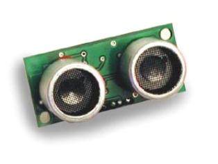
The SRF04 ultrasonic range finder is a small PCB measuring only 43mm by 20mm. It has two transducers attached, one for transmit and one for receive. The illustrations below show the front and rear views of the SRF04.
 |
 |
 |
Connections to the SRF04 are via four of its five PCB pads shown below.
As far as I can tell, there is no polarity protection or voltage regulation on the PCB, so the SRF04 must be supplied with no more than 5 Volts, and the correct polarity must be observed otherwise damage ‘will’ occur.
The TRIGGER pin causes the SRF04 to take a range reading when it is cycled high to low, and must be in the high state for no less than 10us.
The ECHO pin will remain in the high state until an echo is detected. Measuring the length of time that the pin stays high will give us a measure of time in microseconds that we can convert into distance. In order to convert the returned pulse length into centimetres, we need to divide by 36, and to convert to inches we divide by 73.
The full listing for a program to control the SRF04 with the PROTON+ BASIC compiler is shown below. The TRIGGER pin should be connected to PORTB.1 of the PICmicro, and the ECHO pin should be connected to PORTB.0.
Include "PROTON_20.INC" ' Use the PROTON
board with a 20MHz xtal
Symbol TRIGGER = PORTB.1 ' Define pin for
Trigger pulse
Symbol ECHO = PORTB.0 ' Define pin for Echo pulse
Dim RANGE as Word ' 16 bit variable
for Range
Delayms 200 ' Wait for PICmicro
to stabilise
Cls ' Clear the LCD
While 1 = 1
Pulsout TRIGGER,15,HIGH ' Produce a 15us high to low pulse
RANGE = Pulsin ECHO,1 ' Measures the
range in uS
Delayms 10 ' 10ms recharge
period after ranging completes
RANGE = RANGE / 62 ' Use 62 for cm
or 149 for inches
Print at 1,1,"RANGE = ", Dec Range," cm "
Wend
Notice that were using a 20MHz crystal. This is because the resolution of the PULSIN command is simply not good enough for accurate results if a lower frequency oscillator is used. The resolution of PULSIN with a 20MHz crystal is 2us, which is more than enough for good accuracy.
Because we have a 2 microsecond resolution, the division to convert into centimetres or inches has to be doubled. So to convert to centimetres, we divide the returning pulse length by 62, and to convert to inches, we divide the pulse length by 146.
It is possible to break the returned pulse length into fractions of a centimetre or inch, but this is asking a little too much from ultrasonic range finding in general, never mind the little SRF04. However, by utilising the Median filter subroutine discussed earlier, the results from the SRF04 can be made extremely stable, and very accurate.
There’s not a lot else I can say about this module that isn’t shown in the demonstration program above. It really is that simple to use!
One thing that I found really useful was the fact that on the Daventech web site www.robot-electronics.co.uk , you can find the circuit diagram of the SRF04. And with a little modification, the range finder programs discussed earlier will work perfectly with it.
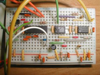
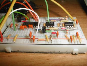
And to prove it, shown below are some pictures of the circuit for the SRF04 built on the PROTON development board’s solderless breadboard area.
 |
 |
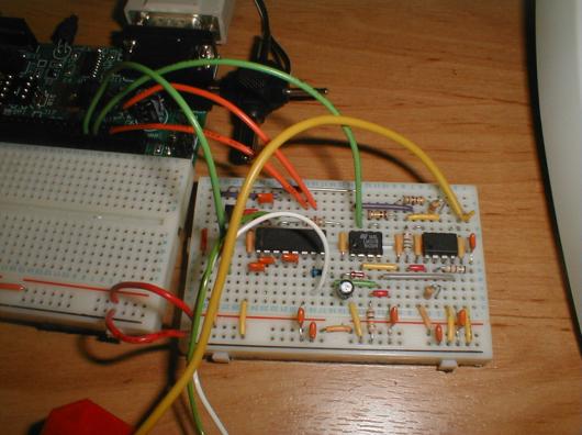 |
OK, so it’s not actually built on the PROTON development board’s solderless area, but the breadboard used is identical.
For ethical reasons, I cannot show the circuit diagram here. And for the same reasons, the circuit should only be used for educational or personal use. The people at Daventech have put a lot of thought into the SRF04, so they deserve our support.
Interfacing with the SRF08.
The SRF08 range finding module is the big brother of the SRF04, and is quite a sophisticated piece of equipment thanks, in part, to the on-board PICmicro and some clever circuitry. Interfacing with the SRF08 is accomplished using the popular 2-wire I2C bus, first developed by Philips for use in domestic appliances. The I2C bus is one of my favourite interfacing methods, so I feel right at home with this little device.
The SRF08 has exactly the same dimensions as the SRF04 which is 43mm by 20mm, and both modules are remarkably similar until you look closer, upon which, you will notice a small CDS light sensor located between the two ultrasonic transducers. So the SRF08 is also capable of measuring light level.
The SRF08 module appears as a Slave device on the I2C bus, with the controlling hardware, the PICmicro in our case, being the Master. And because the I2C protocol calls for open drain outputs, it requires a pullup resistor on both the SDA (Data) and SCL (Clock) pins, as illustrated below.

Ensure that a voltage of no more than 5 Volts is supplied to the SRF08, and that its polarity is observed, or damage ‘will’ occur.
The MCLR pin is not used for standard interfacing and can be left unconnected, but it can also be used to reset the module by briefly pulling it to ground.
The documentation that comes with the SRF08 is reasonably comprehensive, and somewhat involved, therefore it would be rather pedantic to repeat it here. So the best thing to do is to show you some code samples that will interface the SRF08 to a PICmicro using the PROTON+ BASIC compiler.
Upon first using the SRF08, its default address on the I2C bus, commonly called its SLAVE ADDRESS, is set to $E0. So by sending a series of commands to the device with the slave address of $E0, both Light and Range can be ascertained, either in centimetres, inches of raw Time Of Flight data measured in microseconds (uS).
A Light and Range reading is accomplished by writing to the Command Register, which has a value of $00, using the compiler’s BUSOUT or HBUSOUT commands. Then sending, in this case, the instruction for a range conversion in centimetres, which is $51. After this instruction has been sent to the bus, we must wait a minimum of 65ms before asking for the results of the command, note that the length of time to wait can be changed and is well documented in the SRF08 instruction manual.
Busout $E0,$00,[$51] ' Send command for range in centimetres
Reading the values back from the SRF08 entails using the BUSIN or HBUSIN commands. In order to read the light level as well as the range value, we can access the internal register addressed at $01, then by allowing the SRF08 to auto increment its internal address counter, we can automatically take a reading of the range, which is addressed at $02.
Busin $E0,$01,[LIGHT, RANGE] ' Read Light and Range values
A program to read the Light and Range values from the SRF08 is listed below. It uses the PROTON MK2 development board as the building medium, therefore connect the SRF08 SDA line to PORTC.4, and the SCL line to PORTC.3. Ensure that jumpers J7 and J8 are connected to enable the pullup resistors.
' Daventech SRF08 Ultrasonic Range
Finder
' demonstration software for the PROTON+ Compiler Version 2.1
Include "PROTON_4.INC" ' Use the PROTON
Development board
SLOW_BUS = ON ' Slow down the
I2C bus slightly
Dim LIGHT as Byte ' 8-bit Light
sensor value
Dim RANGE as Word ' 16 bit variable
for Range value
Symbol SRF08_NEW_ADDRESS = $E1 ' New Slave Address
Symbol SRF08 = SRF08_NEW_ADDRESS ' SRF08 I2C Slave
Address
Symbol CMDREG = 0 ' SRF08 Command
register
Symbol LIGHTREG = 1 ' SRF08 Light sensor register
Delayms 200 ' Wait for PICmicro
to stabilise
Cls ' Clear the LCD
' Change the SRF08 address. Call this once with a single SRF08 connected.
Gosub CHANGEADDRESS
While 1 = 1 ' Create an
infinite loop
Busout SRF08, CMDREG, [81] ' Send command for range in centimetres
Delayms 66 ' Wait for range to finish
Busin SRF08, LIGHTREG, [LIGHT, RANGE] ' Read the light level and the
range
Print at 1,1,"LIGHT = ", Dec LIGHT," " ' Display the light level
Print at 2,1,"RANGE = ", DEC RANGE, " cm " ' Display the
range
Wend
A fixed slave address of $E0 would cause a problem if more than two SRF08 modules were connected to the same bus. But Daventech have thought of this scenario and allow the slave address of each module to be changed through software.
A small program to accomplish address changing is listed below. The program changes the slave address from the default $E0 to $E1, then starts taking light and range readings. Again, it uses the PROTON MK2 development board.
' Daventech SRF08 Ultrasonic Range
Finder
' demonstration software for the PROTON+ Compiler Version 2.1
'
' Change the Slave Address of the SRF08 module.
Include "PROTON_4.INC" ' Use the PROTON
Development board
SLOW_BUS = ON ' Slow down the
I2C bus slightly
Dim LIGHT as Byte ' 8-bit Light
sensor value
Dim RANGE as Word ' 16 bit variable
for Range value
Symbol SRF08_NEW_ADDRESS = $E1 ' New Slave Address
Symbol SRF08 = SRF08_NEW_ADDRESS ' SRF08 I2C Slave
Address
Symbol CMDREG = 0 ' SRF08 Command
register
Symbol LIGHTREG = 1 ' SRF08 Light sensor register
Delayms 200 ' Wait for PICmicro
to stabilise
Cls ' Clear the LCD
' Change the SRF08 address. Call this once with a single SRF08 connected.
Gosub CHANGEADDRESS
While 1 = 1 ' Create an
infinite loop
Busout SRF08, CMDREG, [81] ' Send command for range in centimetres
Delayms 66 ' Wait for range to finish
Busin SRF08, LIGHTREG, [LIGHT, RANGE] ' Read the light level and the
range
Print at 1,1,"LIGHT = ", Dec LIGHT," " ' Display the light level
Print at 2,1,"RANGE = ", DEC RANGE, " cm " ' Display the
range
Wend
'----------------------------------------------------------------------------
' This subroutine will change the SRF08's I2C address to whatever you
have set
' in the SRF08 SYMBOL statement above. Since we don't know the current
address
' of the SRF08, we use the General Broadcast address (00) to communicate
with it.
' Make sure you only have one SRF08 connected when you do this.
' The new address is stored on the SRF08, so this only needs to be done
once.
CHANGEADDRESS:
Busout $E0, CMDREG, [$A0] ' \
Busout $E0, CMDREG, [$AA] ' Required Sequence to change Address
Busout $E0, CMDREG, [$A5] ' /
Busout $E0, CMDREG, [SRF08_NEW_ADDRESS] ' Send new Slave Address
Return
Don’t forget to keep a note of the new slave address for future reference.
I hope I’ve wetted your appetite for some serious experimenting with ultrasonics, either building your own or using a ready made module. But above all, have fun while your doing so.
| Author: Les Johnson | First Pubished 2003 Crownhill Associates Limited |
All rights Reserved
|