PROTON Plus PICBASIC COMPILER
Ultrasonic Range Finding.
Practical Circuit Design
Of course, we cannot possibly hope to create anything as sophisticated as a side scan SONAR used for wreck location, but using a handful of common components and a little BASIC code, we can add object detection and distance measurement to a future project simply and efficiently.

For all our experiments, we’ll be using readily available 40KHz ultrasonic transducers. These come as a pair with one being optimised for transmission and the other for reception. An illustration of the transducers used in the experiments is shown to the right.
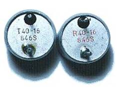
It is important to identify which is which as any subsequent results may suffer. The transducers used were clearly marked on the underside, but I am unsure if this is a common practice among these types of transducers.
As their name implies, these devices operate at a frequency of 40KHz, which is nearly three times higher than the best human hearing, so we don’t have to worry about noise pollution. This frequency is also above the range of dogs and cats hearing, so you won’t harass your pets.
 The circuit for our range finding experiments is shown
below.
The circuit for our range finding experiments is shown
below.
As you can see, the circuit is remarkably simple, consisting of two ICs (U1a and U1b are in the same 8-pin package) and a handful of common value discrete components.
Receiver circuit explanation.
The signal picked up from the ultrasonic transducer is extremely small, so in order to be of any use it needs quite a significant amount of amplification. ICs U1a and U1b form a standard high gain preamplifier, with U1a having a gain of 10 set by resistors R1 and R2, and U1b having a gain of 100 set by resistors R4 and R7. So altogether they form a pre-amp with a gain of 1000 (10 * 100). Remember that both these ICs are enclosed in the same 8-pin package.
There is no need for a coupling capacitor for the input of U1a, as the transducer can be thought of as a type of capacitor, therefore it does not present a resistive load.
Resistors R5 and R6 together with capacitor C2 form a potential divider that supplies the op-amps with half the voltage rail. This commonly named ‘floating ground’ eliminates the need for a negative supply that usually frightens people away from using op-amps.
The output of U1b is now sufficiently large enough to be useful, but is not suitable for interfacing directly to the PICmicro microcontroller. The PICmicro expects a clean high or low on its IO pin, but the output of the op-amp is an amplified AC signal with a midpoint voltage of approximately 2.5 Volts. This is were the clever part of the circuit comes in. In order to convert the AC signal into discernable highs and lows, we use an LM393 comparator (U2).
A comparator works by comparing the voltage on its two inputs, if the +ve input is more positive than the -ve input, the output will be high, but if the +ve input is more negative than the -ve input, the output will be low. Without any input signal to the pre-amplifier, the output of U1b will be a steady DC voltage of approx 2.5 Volts. This is fed directly to the +ve input of the LM393 comparator. The same voltage from U1b’s output is also fed through VR1 and R8 to the -ve input of the comparator, however R9 connected to ground makes this network function as a potential divider thus reducing the voltage. So the voltage on the -ve input is slightly lower than the +ve input, and the output is high, this is the 'no obstacle state'. When an echo is received, an amplified version of the signal appears on the output of U1b and is fed to the +ve input of the comparator which now goes both higher and lower than before as the AC signal is super-imposed on the original DC voltage. However, the -ve input is fed through the resistor network VR1, R8 and R9, and has C3 connected to ground, this makes a low-pass filter, removing all the signal and maintaining the same DC voltage as before. So, if the received signal on the +ve input should go lower than the voltage on the -ve input the comparator output will go low, and the output from the comparator will be a series of negative going pulses just right for connecting to the PICmicro.
By adjusting VR1, the voltage difference varies between the +ve and -ve inputs of the comparator and makes it more or less sensitive. This overcomes any problems from the rather unsophisticated op-amp pre-amplifiers, and makes the circuit somewhat self adjusting as it will automatically compensate for any gain variations.
Transmitter circuit explanation.
The most involved part of the range finder is the receiver, but transmitting the 40KHz signal is just as important but very straightforward as the PICmicro does most of the work for us.
We need to transmit as large a signal as possible in order to carry enough energy to have a portion of it reflected back to the receiver. To do this, we drive the transducer in a simple form of push-pull setup. This ensures that the transducer is operating with both cycles of the 40KHz wave. The illustration below shows this: -

The waveform entering the base of the transistor is our 40KHz signal produced by the PICmicro. This is then amplified by the transistor and produces a two phase output on its emitter and collector. When one is pushing, the other is pulling. i.e. out of phase by 180°. We are still only driving the transducer at 5 volts, but the above method imitates a drive of nearly double that. This arrangement will give us an effective range of a little over 2 metres, which is more than enough to experiment with, and indeed enough for most applications.
Both the circuit and the software are designed around the Crownhill PROTON Development board. This offers a comfortable an efficient method of developing a PICmicro project. However, this is not mandatory and the circuit can be built using any medium.
The PROTON Development board has a PIC16F877 PICmicro device at its heart, and attaches to a 2*16 line Alphanumeric LCD which we’ll use to display the results. It also has a solderless breadboard area where we can build our circuit. The layout of the ultrasonic range finder on the solderless breadboard area is shown overleaf.
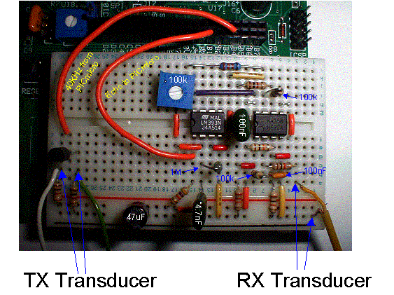
It’s surprising what can be squeezed on to the small breadboard with a little care, the secret is the Wire Jumper kit also available from Crownhill. This offers both tidiness and repeatability as each wire length is colour coded differently. Anyway, a different angle photograph of the same board layout is shown below in order to clarify any obscured components in the picture above.
