|
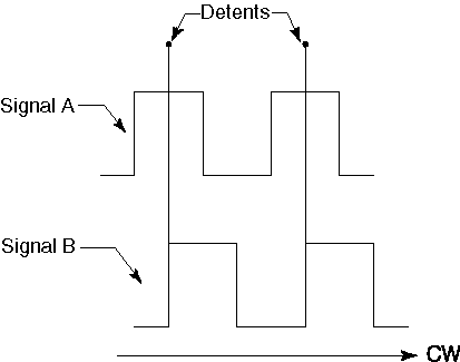
A rotary encoder detection circuit is necessary to allow the user to change the parameters of the audio effect in real time. This circuit will detect when a change is made to the rotary encoders located on the front panel of the unit so that the parameter being controlled by that encoder can be updated. The 2-bit incremental encoder delivers two signals that convey information about the amount of shaft rotation and the direction of rotation. Tracking the relative phases of signals 'A' and 'B' determine both rotation and the direction of the rotation over one rotational tick cycle. A rotational tick cycle will be defined as the rotational movement from one detent to the next. Since the Panasonic EVQ-WTE series rotary encoders contain 30 detents per full rotation, a rotational tick will be 12° of rotation.


Finally both signals 'A' and 'B' are logic high (position 5) and the encoder will come to rest on a detent with signal 'A' high and signal 'B' in an unknown state (position 1). The most natural way to decode this sequence is through the construction of a finite state machine. Since we only need to detect the direction of rotation and that a rotation has occurred, some of the transition states can be disregarded. For instance, we know that if we first receive inputs of 'not A' and 'B' from the home position that a counterclockwise rotation must be taking place. Likewise if we first receive inputs 'not A' and 'not B' a clockwise rotation must be in progress. Unfortunately, the determination of the first state alone is not enough information to decode the rotary encoder. Since we would not want a partial rotation or spurious noise to be acknowledged as an actual count, we must be certain that both the clockwise and counterclockwise sequences transition into their next expected states.

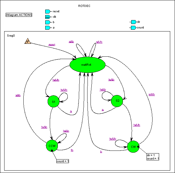
Now that we have determined that we can detect both rotation and the direction of rotation by tracking the transitions through five possible states, we can build a model of a finite state machine. In the state machine model shown below, we start in the 'waitRot' state. This state represents the home position and it is the position where the system will startup in and return to after a successful or unsuccessful rotation, or when the reset is asserted. From this position all of the possible combinations of signals 'A' and 'B' are accounted for, but only the combinations 'not A' and 'not B' or 'not A' and 'B' will result in a departure from the 'waitRot' state. If an input of 'not A' and 'not B' is received, we will transition into state 'S1' and as long as the input remains unchanged, we will remain in this state. While in this state, if signal 'A' rises before signal 'B' falls, an error has occurred and we must return to the 'waitRot' state. If, on the other hand signal 'B' falls before signal 'A' rises we will transition into the 'CW' state. It is upon the entry to this state that a clockwise rotation will be acknowledged and the 'count' signal will be asserted. The 'count' signal will remain asserted until either signal 'A' rises or signal 'B' falls or a 'reset' occurs. Then the system will return to the 'waitRot' state.
 To generate a counterclockwise rotation, we first transition from 'waitRot' into state 'S2' on a 'not A' and 'B'. Upon entry into state 'S2' the output 'dir' will be asserted. The output 'dir' is pre-asserted in order to guarantee that we will meet the set-up time for any logic that will rely on the 'dir' and 'count' outputs of this state machine. In order to implement the "ROTDEC' state machine as a
Xilinx Foundation schematic macro, we need to generate and synthesize the
code using the Foundation State Editor. The following is the listing for
the generated ABLE code that implements the 'ROTDEC' state
machine.
Once the 'ROTDEC' state machine macro is created it can be dropped into a top-level schematic design and be interfaced to the buffered input pins from the rotary encoder. The 'reset' input is synchronized to the 12.288MHz clock and is used to force the state machine into the 'waitRot' state after the 'count' signal has been asserted. The state machine is clocked from a relatively slow clock source in order to allow the rotary encoder's mechanical contacts a chance to debounce. The COUNT10 clock represents a clock period of:

This was found to be a good clocking frequency by trial and error, since it offers nice high rotational speed tracking combined with a low switch bounce error rate.

The approximate FPGA resource utilization for each rotary encoder detection circuit is 3 configurable logic blocks. |
|||