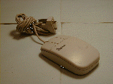


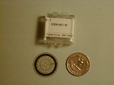
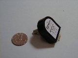
Incremental optical encoders can be quite expensive. The bottom two photos are commerically available units from US Digital. The left is a $7 USD mylar encoder disk and the right is a $50 USD encased encoder. A US quarter is shown for scale.
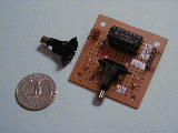
Taking apart the ubiquitous $5 PC mouse (top left), however, can give you two cheap but quite reliable encoders plus two infrared (IR) emitter-detector pairs. This tutorial will show you how to take apart a mouse, remove these parts and protoboard your own quadrature encoder (top right) in an afternoon or two.
This tutorial is broken down as follows:
| PART DESCRIPTION | VENDOR | PART | PRICE (1999) | QTY |
| SERIAL PC MOUSE | JAMECO | 48004 | 0.29 | 1 |
| 7414 HEX INVERTER | DIGIKEY | DM7414N-ND | 0.83 | 1 |
| 14-PIN WIREWRAPPING SOCKET | DIGIKEY | ED4314-ND | 1.60 | 1 |
| 47 OHM RESISTOR | 2 | |||
| 30 KOHM RESISTOR | 2 | |||
| SMALL PROTOTYPE BOARD | 1 | |||
| HEADERS | DIGIKEY | |||
| HOUSING | DIGIKEY | |||
| CRIMPS | DIGIKEY | WM2200-ND | ||
Over the years you might have a collection of mouses that are not being used. The one used in this tutorial was a serial (9-pin RS-232) style Genius mouse. These can be bought at any CompUSA or any mail-order PC store.
Headers, housings and crimps were used for quick and professional looking connections. Example Digikey part numbers are WM4002-ND (headers), WM2002-ND (housings), WM2200-ND (crimps) and WM2312-ND for crimp tool. Of course, you can choose to wirewrap/solder your circuit without these parts.
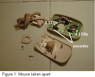
Figure 1 shows the internal circuit once the mouse's screws are removed. You should see two black-colored plastic encoder disks. Each disk is surrounded by 4 LEDs (two IR emitters and two detectors). This particular mouse has 32-slot encoder disks.
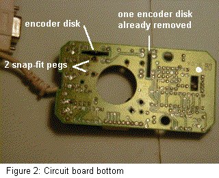
Flipping over internal circuit shows, Figure 2, that the encoder disks are snap-fitted. The encoder is difficult to pry off without some dremel'ing. Carefully shaving some the plastic off makes it easier to pry the encoders off with a screwdriver as shown in Figure 3.

The IR emitters and photodetectors can be removed using a desoldering tool. Figure 4 shows two pink and two clear LEDs that surround each encoder disk. LEDs connected to resistors are the emitters. Visually inspecting the traces for this particular mouse revealed that the pink ones are the emitters. The clear ones are photodetectors.
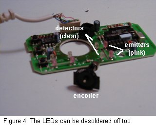
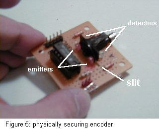
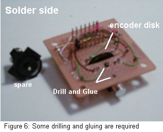
Figure 5 shows the encoder physically mounted on the prototyping board's edge. A dremel cutting disk was used to mill out a thin slit. This slit must be thick enough so that the encoder disk can freely rotate. You must also drill holes into the prototyping board to allow the encoder's snap-fit pegs to pass. The pegs are then glued down (see Figure 6). The emitters and photodetectors were then soldered as depicted in Figure 5.
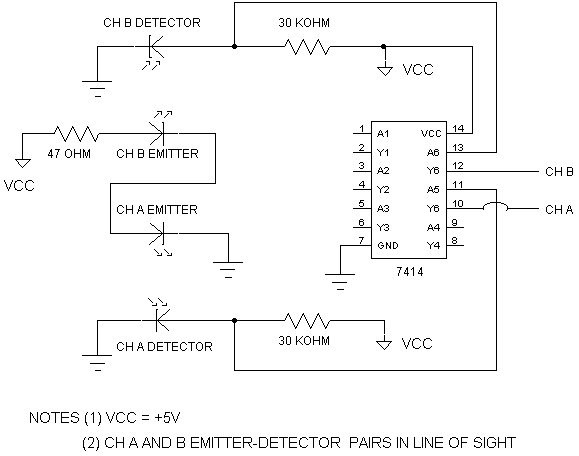
mouseHackSchematic.pdf is the Acrobat file of the same schematic. You will need Adobe's free Acrobat reader to view it.
The schematic is straight-forward. Only two inputs (pins 11 and 13) of the 7414 hex inverter are used. This ensures that outputs (pins 10 and 12) go logic high (+5V) whenever the detector sees the emitter and low (0V) when occluded.
This is explained by appreciating that current will always attempt a flow with paths of least resistance. In the unblocked emitter-detector case, current will flow through the detector towards ground and make pin 11 (and/or 13) have 0 volts. Correspondingly, pin 10 (and/or 12) will measure +5V. Conversely, in the blocked case no current flows through the detector and forces pin 11 (and/or 13) to be +5V, with a corresponding pin 10 (and/or 12) output of 0V.
Quadrature, the technique of measuring both rotation angle and direction (clockwise or counter-clockwise), requires two emitter-dectector pairs. Each detector provides a channel. The schematic denotes the detector outputs, 7414 pins 10 and 12, Channels A and B respectively. These output pins are wirewrapped to header posts for quick and easy connections to oscilloscope probes or encoder measuring devices. Your circuit will work without headers, housings and crimps, but they are convenient, aesthetic and reasonally priced (e.g. see Table 1 Digikey part numbers).
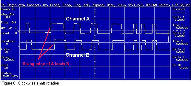
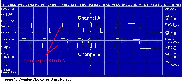
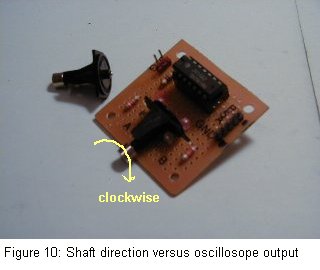
Figure 8 and 9 are screenshot JPEGS of an oscilloscope display, when rotating the encoder disk clockwise and counter-clockwise respectively (see Figure 10). In each figure, the top square wave corresponds to Channel A and the bottom square wave is Channel B.
You can observe the phase difference between the two square wave; the rising edge (i.e. transition from 0 to +5V) of Channel A comes before (lead) or after (lag) Channel B. This is quadrature in action, whereby phase lead or lag indicates disk direction. The disk rotation angle is determined by the number of Channel A (or B) rising (or falling) edges. For example, in Figure 8, there are 8 rising edges. Thus 8 slots in the encoder disk have passed between the Channel A emitter-dectector pair.
As mentioned previously, this mouse encoder disk has 32 slots. Thus one disk rotation (360 degrees) will generate 32 rising edges. Thus for Figure ??? the disk rotated 8 slots * 360 degrees / 32 slots = 90 degrees. The square waves in Figures ??? and ??? have variable width. This is because the disk was rotated by finger at a non-constant velocity.
The oscilloscope output demonstrates that the circuit and quadrature works as expected. To use your new encoder practically, you'd want to add an up-down counter circuit (from flip-flops say) with perhaps several 7-segment LED displays.
There are quadrature clock converters like Hewlett-Packard/Agilent's HCTL-2000, HCTL-2016, and HCTL-2020 or LSI's LS7083 and LS7084.
LSI also sells 24-bit single chip quadrature/counter solutions, namely the LS7166 and LS7266. These are typically used if you wish to interface encoders to PC's or embedded microcontrollers over an 8-bit bus. A future tutorial on building your own ISA-bus based quadrature encoder card will be shortcoming.
Some "big picture" applications include measuring: mobot wheel position and speeds, inverted pendulum angles, telescope pointing, and XYZ-table positioning.
Click here to email me