
Application Note
The disk of an incremental encoder is patterned with a single track of lines around its periphery. The disk count is defined as the number of dark/light linepairs that occur per revolution ("cycles / revolution" or "c/r"). As a rule, a second track is added to generate a signal that occurs once per revolution (index signal), which can be used to indicate an absolute position.

To derive direction information, the lines on the disk are read out by two different photo-elements that "look" at the disk pattern with a mechanical shift of 1/4 the pitch of a linepair between them. This shift is realized with a "reticle" or "mask" that restricts the view of the photo-element to the desired part of the disk lines. As the disk rotates, the two photo-elements generate signals that are shifted 90° out of phase from each other. These are commonly called the quadrature "A" and "B" signals.The clockwise direction for most encoders is defined as the "A" channel going positive before the "B" channel.
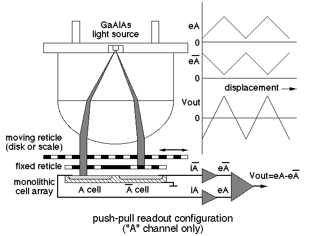
If the readout of the disk is obtained by a single photo-element for each of the A and the B channels, it is called a "single-ended" readout. This type of readout generates signals that are very susceptible to disk runout ("wobble"), slight imperfections in disk etching etc. A much more effective and accurate readout system is called "push-pull" where the A and B channels are generated by two photo elements for each channel.
The push-pull readout synthesizes the A and B channels by combining two individual signals for each of the channels, generated by photo elements that are shifted by half the pitch of a linepair. This way, when one photo-element looks at a dark line, the other is fully illuminated. The resulting signals are combined in an amplifier or in a comparator with a significant increase in stability and accuracy. All COPI incremental encoders are constructed with push-pull readouts.

All optical encoders are inherently analog devices. The disk or scale moves with a finite speed and gradually cuts off or admits light to the photo-elements.
If the second stage in the diagram above has finite gain (e.g. a differential amplifier), the A and B signals will be sinusoidal (triangular for low counts per revolution). If the second stage has infinite gain (e.g. a comparator), the output will be a digital pulsetrain with state changes defined by the crossover between the cellpairs that form the A or B channel.
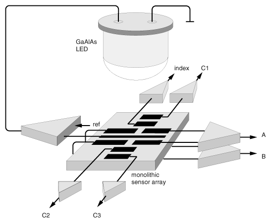
In order to stabilize the LED, which has a severe negative temperature
gradient (Å - 0.8% per °C), and allow digitizing and differentiation of
the signals of the sine/cosine encoders (see "infinite resolution
encoders",CP-200, CP-300 & CP-800), COPI adds for most of their
encoder models a separate feedback channel to achieve constant light
levels over time end temperature. The following shows the standard COPI
electro-optical configuration:

Literature Request | Samples | Contact Us | Corporate Sites | Directions
24 Dec 1996