|
 Rotary encoders make versatile Rotary encoders make versatile
motion feedback
devices
Online
extra: Rotary
encoders provide variety
‘Encoding" or
converting angular position into electronic signals is the
mission of rotary encoders. Ways to detect motion include
mechanical (via brush contacts) or magnetic/inductive methods,
but noncontact optical encoders comprise the most common
feedback device used in industrial motion control.
|
Besides motor shaft position, rotary encoders
also provide information for speed feedback, direction
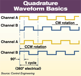
of rotation (see diagram), and electronic commutation in
brushless servo systems. Position feedback is not
limited to the motor. For example, an encoder can
indicate valve position or sometimes be directly mounted
to a rotary load.
All
optical encoders work on the same basic principle. Light
from an LED or other light source is passed through a
stationary patterned mask onto a rotating code disk that
contains code patterns (see below). The disk is the
heart of the device. Photodetectors scan the disk and an
electronic circuit processes the information into
digital form as output to counters and
controllers.
Incremental
or absolute
Two basic types of optical
encoders exist—incremental and absolute position.
Incremental encoders are the simpler devices. Their
output is a series of square wave pulses generated as
the code disk, with evenly spaced opaque radial lines on
its surface, rotates past the light source. Number of
lines on the disk determines the encoder’s
resolution.
The
simplest incremental encoder, called a tachometer, has
one square wave output and is often used in
unidirectional applications in need of basic position or
speed information. The more useful quadrature encoder
has two output square waves (Channels A and B), plus a
reference pulse (Channel Z) generated as a "home" marker
once each revolution (not shown in
diagram). |
|

|
|
A
two-channel (quadrature) incremental encoder can
sense direction of rotation as well as angular
position. The signals’ phase relationship, offset
by 90 electrical degrees, is related to
direction—clockwise if Channel A leads Channel B,
and vice versa.
| |
Incremental encoders provide only relative position; in
case of power failure, the position count is lost. The Channel
Z marker comes into play upon a restart to establish the home
position, so that the new pulse count can begin.
Absolute
position encoders are more complex and capable than their
incremental cousins. They provide a unique output for every
position. Their code disk consists of multiple concentric
"tracks" of opaque and clear segments. Each track is
independent with its own photodetector to simultaneously read
a unique position. The number of tracks corresponds to the
binary "bit"-resolution of the encoder. That is, a 12-bit
absolute encoder has 12 tracks.
Also, the
absolute encoder’s nonvolatile memory retains the exact
position without need to return to "home" position if power
fails. This is useful in remote applications where equipment
runs infrequently with power turned off between
uses.
Most
rotary encoders are single-turn devices, but absolute
multiturn units are available, which obtain feedback over
several revolutions by adding extra code disks. The additional
disk stages are geared to the main disk and have their own
photodetectors.
Choice of
incremental or absolute encoder is very application dependent,
but price is a factor. Incremental encoders are less costly
than "absolutes," but generally offer fewer functions and
lower resolution. They’re also more susceptible to electrical
noise.
Some
techniques can improve resolution and noise immunity. A
controller counting the leading and trailing edges of Channel
A allows the quadrature detection method to multiply basic
encoder resolution by 2X. If this is done for both Channels A
and B, 4X basic resolution is obtained. However, system
bandwidth limits must be kept in mind.
Open-collector is one type of output circuit from an
incremental encoder. The user must specify a pull-up resistor
for this electronic interface to work properly with external
controls. Another basic output circuit, the differential line
driver, is used with long cable lengths and in electronically
noisy environments. Complementary (differential) signals
generated with this output take on an incorrect form in the
presence of electrical noise. Information coming from these
abnormal signals can then be rejected.
Absolute
encoders work with various serial outputs that can be
converted to parallel and fieldbus formats. Rotary encoders
offer a rich variety of sizes, features, and capabilities.
Models with speeds up to 30,000 rpm and operating temperatures
well above 100 °C are available. For more information and
product examples see July
Online issue under this topic at
www.controleng.com.
| 
