
This is a re-work of an article I wrote and which was published in Archive (an Acorn specific subscription magazine) in September 1995. It is of general interest so is included here.
Open up a mouse and inside it you will find two wheels, each one similar to the first drawing. The wheel is usually made of black plastic with rectangular slots punched in it. I have shown only 6 slots at 60° spacing but they are a lot closer and many more. Shining through the slots are two LEDs (light Emitting Diodes) shown by the black dots. Each LED shines on to a light sensitive transistor. The two emitters are spaced so that, when one transistor can 'see' its LED through the centre of its window, the other LED is looking at an edge and is therefore switching on or off. In my illustration the LEDs are spaced at 105° (60° x 1.75). The output voltage from the transistor is processed to switch rapidly from high to low as the LED's light is transmitted or occluded so that the voltage is low when the transistor is lit and high when it is in darkness. In the diagram LED A is fully illuminated and LED B is switching. Note that LED B may be switching from light to dark or from dark to light - this depends on the rotation direction.

Now consider the second drawing. Here the wheel is shown in 4 different states, each 15° rotated from the last. Diagram E is equivalent to diagram A, being 60° rotated. For clockwise rotation the states follow each other in order A-B-C-D-E from left to right but if you read the states from right to left, E-D-C-B-A, then these correspond to anticlockwise rotation.

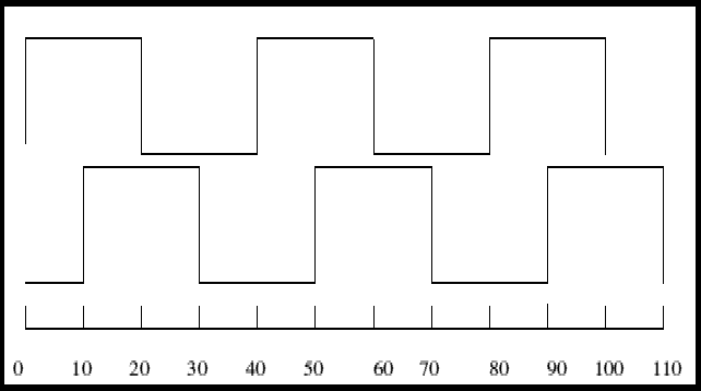
Notice that LED 2 is changing state from light to dark in diagram A for clockwise rotation and in diagram C for anticlockwise rotation. So if we measure LED1 everytime LED 2 goes from light to dark, if LED 1 is light then we are rotating clockwise but if LED 1 is dark, then we have anticlockwise rotation. The computer uses this fact to monitor direction: each time LED 2 goes from light to dark it samples LED 1 to determine the direction. It uses the number of transitions to measure the distance. In practise the system s a little bit more clevr since where are problems if the wheel stops on an edge. Or course the two LEDs are interchangeable and it doesn't matter which one is used as the step and which as the direction. If, in re-wiring you get the two signals interchanged, the mouse will simply work upside down or left to right instead of right to left. The diagram below shows the corresponding electrical signals switching at 15° intervals.

There are two such wheels, one rotates for vertical movement and the other rotates for horizontal movement of the mouse ball. If you take your mouse to pieces you can easily see these two 'encoders'. The actual wheels have a lot more slots than I have shown.
I am not a computer engineer so my involvement with mice was driven solely by need. Add this to the fact that Acorn machines have a proper hardware mouse interface built is and do not use the very mixed selection of IBM type mice and you will see there is little point in asking me questions about serial and other sundry mice.
However you can try ST Developments who does a PIC interface to match a PS2 mouse to Risc OS computers.
About Risc OS computers and how they differ from Wintel machines.
Click here to return to 4QD's home page of Speed Controllers for Battery Operated Motors.
© 1996-2000 4QD