EE498 Spring 1996
By William Winston
and
Andrew Lundberg
To get to any given destination there can be several different paths, and each of these paths has different characteristics, challenges, benefits and disadvantages. You are also given the choice to accept input from others' travels or to attempt to find your way alone. This lesson was learned through the process of designing a power line appliance controller and through the dissection and analysis of a commercially available model (X-10). We were interested to see how close our design would be to what is actual sold.
As was expected our design was different than that of the X-10. These differences ranged from fundamental operation concepts to implementation details. However, many of the problems that we encountered, clearly were issues that they had faced in their design process. All in all, a true engineering experience was gained. A concept was realized, developed, planned, and actualized, and through comparison to professional work we were able to gain a better appreciation to what it takes to design consumer electronics.
The following is a detailed description of our final design and how it worked, as well as a description of the X-10 and the basis of its operation. The two are then compared and contrasted on the predefined criteria.
Final Design Implementation
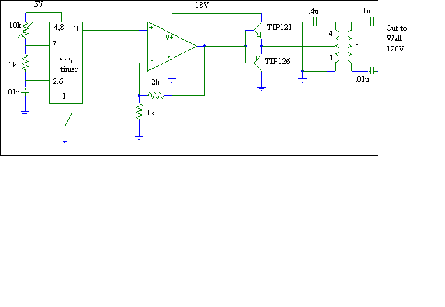
Our final design was the same as our original proposal in concept. However, the actual way we implemented our ideas had to change due to the components limitations. Our final design was broken down it to the following parts: the oscillator, the output stage, the coupling filter, the power supply, and the receiver.
The Oscillator
The oscillator we used was still a 555 timer. However, we could not run it well at 40 kHz due to limitations in duty cycle. The down time was to small to follow with any available op-amp. Instead, new components were selected to make it run at 26 kHz. As mentioned in the proposal the fact that the 555 timer produces a square wave was not a problem. We were able to tune the rest of the circuit to pick out the fundamental frequency of the wave.
The Output Stage
In the original design for the circuit we included a single op-amp in a voltage following configuration as an output stage to the filter. This design, however, had to be totally redone. First, the output from the 555 timer is only 0 to 5 volts. Because of our filters, this was too small and had to be increased. Therefore, we used the op-amp in an non-inverting configuration to increased the amplitude of the square wave. The second problem was that the first op-amp chosen to do this did not have a fast enough slew rate and could not produce a square wave out at 26 kHz. This problem was solved by simply changing op-amps. The final set back in this stage was the amount of current that the op-amp could produce. In the event that multiple receivers were being used or from lossy line, we wanted to be able to supply ample current. For this reason, a class B output stage was used before the signal goes to the coupling filters.
The Coupling Filter
The first coupling filters proposed simply did not block the 60 Hz line signal from coming back into the circuit well enough. Several other design were considered but the final version was a center tapped transformer with tuning capacitors, see the schematic for actual implementation. This method allowed us to tune to filter for the frequency of our choice. This design had a great attenuation of the 60 Hz line signal. Therefore, the 60 Hz signal did not interfere with our circuit. These transformers were not easy to find, so we hand wrapped two ourselves. The 1:1 ratios had 10 turns each and the 4:1 had 40 turns. In practice one of these would be used for an output filter and one for an input filter. However, for demonstration purposes, we used only one to show that the concept will work. In hind sight it would make more sense to use a sinusoidal oscillator instead of a square wave because of the band pass nature of the coupling. This would allow the bulk of the energy to get through the filter instead of losing the high frequency components of the square wave.

The Power Supply
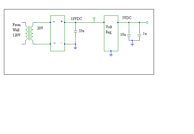
The power supply has two main functions. First, it needs to supply the 555 timer with 5 volts to operate. Second, it produces 18 volts to drive the op-amps and the output stage. The 18 volts is obtained by first stepping down the 120 volts AC to 20 volts AC. Then it is rectified. Capacitors smooth out the signal, and hold it at about 18 volts. The 5 volts is produced using a voltage regulator and capacitors.

The Receiver
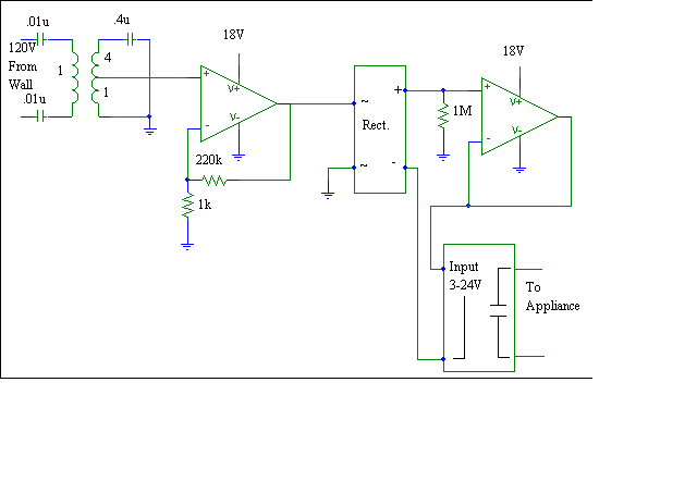
Again, the basic concept of the receiver was the same as first planned but the actual implementation was different. First, the coupling filter mentioned earlier was used to pick out the command signal sent by the 555. But, because of the sharp attenuation of this filter we needed to amplify even the band passed frequencies. To do this another non-inverting op-amp was used. The relay needs 3 to 24 volts DC, so the amplified signal was sent through a rectifier. The relay also required more current then the rectifier could supply, so a voltage following op-amp was used to drive the relay on and off. One extra resistor was added to the output of the rectifier. And, that was to drop the voltage down to ground when the command signal was not present. If this final resistor was not there, the input to the voltage follower could not discharge and the appliance would stay on. Therefore, the resistor is needed to help turn it off. When the relay is activated, it closes the path for the appliance and it is turned on.

The X-10
The X-10 block diagram for the transmitter and receiver was essentially the same as our design. However; the implementation was quite different. It uses a coded output signal at a much higher frequency and a much higher internal drive voltage. The receiver used a SCR as a switch and a tunable receiver to differentiate between different control commands.
Comparison
The Oscillator
The purpose of the oscillator in the two systems was the same but they differed in two key aspects. The first and most significant was the wave form. While our design used a square wave for implementation simplicity, the X-10 used a sinusoidal wave. This becomes important when looking at power transmission through filters. The second difference was in the carrier frequency. The X-10 used a frequency of 122 kHz where we used a frequency of 26 kHz. This higher frequency allows for easier filter application.
The Output Stage
The difference in the output stages make was very predicable. We amplified our signal to the maximum reasonable voltage of 15 volts so that our transmitting power would be adequate (it was not). The X-10 boosted there signal to 100 volts peak to peak to compensate for this problem. The signal was also coded by bursting the carrier frequency in 1 msec pulses. However, we were not able to identify the exact differences in the various signals.
The Coupling Filter
The coupling filter was the most exciting similarity of the two designs. Both designs used a coupling transformer that filtered everything but the control signal. It is clear that the attenuation problems that we encountered with this element were addressed by the X-10 as well. They had a loss of about 90% of their signal through the coupling and we lost about a 93% of ours. This makes even more sense when you consider the fact that we used a square wave instead of a sine wave and therefore should lose more signal.
The Power Supply
The power supply in the two systems are essentially the same except for the obvious difference that they had a 100 volt dc supply available where we had only 18 volts dc.
The Receiver
The receiver was the most different part of the two systems. The first major difference was that the X-10 did not need a control signal present to remain turned on. Instead, the X-10 used a modified toggle switching network. It would turn on with one signal and stay on until it was commanded to turn off with a different signal. Our receiver on the other hand require that the control signal be present the entire time the appliance was to be on. The second main difference was how each receiver supplied power to the appliance. The X-10 used an SCR to act as the switch for the appliance. However, our design used a DC voltage controlled relay. The SCR was definently cheaper, but it is a limiting factor in the amount of power it can supply to the appliance.
Final Thoughts
Several important lessons were learned durning the course of this project. We will share these insights for those who might follow in our footsteps.
1) Brocasting high frequencies on powerlines is very noisy. It gets on to everything and makes analyzing small signals very difficult.
2) When designing from scratch be very open to input from others. They will see problems that you never considered.
3) Be flexible. Change is ok when it makes something work better.
4) The ground on a scope probe is real ground. Do not connect it directly to the wall outlet!
Revised Equipment List
Oscilloscope
Vector Signal Analyzer (HP89410A)
Power Supply
Digital Multimeter
Function Generator
Breadboard
Circuit Components
Tools
House Outlet
X-10 Powerhouse Transmitter and Receiver